Quick Start Guide Minipack PS System 356808.103, 1v2-2008-10
25
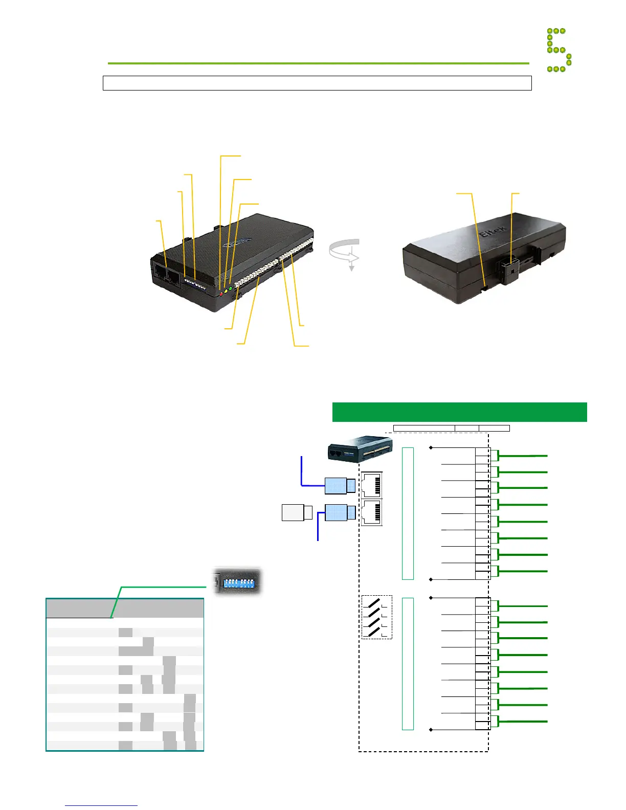
Load Monitor CAN Node
The Load Monitor CAN Bus Node enables you to decentralize and increase the number of input
fuse monitoring and current sense signals in your Smartpack based DC power supply system. The
fuse monitoring inputs are suitable for monitoring a wide range of breakers in both positive and
negative DC distributions.
Read also the “Installation Guide
Load Monitor CAN Node”,
document 351506.033.
CAN Bus Nodes Appendix
RJ45 CAN bus termination plug, if the Load
Monitor is the last node in the CAN bus
(Customer Connections)
1.
 Loading...