Quick Start Guide Minipack PS System 356808.103, 1v2-2008-10
9
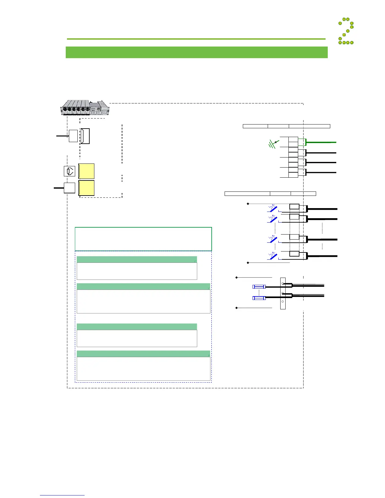
Connections, Factory Settings, etc
The schematic shows the connection terminals in Minipack PS Systems. Or refer to specific
drawings included with your system.
Installation
6B
Load Circuit 2
MCB8
Load Circuit 8
MCB10
Load Circuit 10
(Minipack systems with 6 rectifiers
have 8 DC load outputs available.
Systems with 4 rectifiers have 10
DC load outputs)
Common
Battery “Rail”
Battery
Fuses
Fb1
Fbx
Battery Cables, string 1
Battery Cables, string x
M6 screws, cable lugs
max. 15 mm width
X7A
Interface Cards Connections
Refer to the connections for the actual terminal circuit boards
installed in your system
Battery Connections (X4)
Terminal Circuit Board, Art. 200576
Battery Symmetry 1-4 and Temp. Sense 1
(See page 20 for pin-out information)
Battery Connections, Extended (X3)
Terminal Circuit Board, Art. 200576
Batt. Symmetry 5-8, Temp. Sense 2, Batt. Current and Batt. Fuse Fail
(Not applicable for Smartpack RS232 D-Sub option, on rear panel)
(See page 20 for pin-out information)
Alarm Outputs & Digital Inputs (X1)
Terminal Circuit Board, Art. 218470
Digital Input 1-2 and Relay Output 1-2
(See page 21 for pin-out information)
Alarm Outputs & Digital Inputs Extended (X2A & X2B)
Terminal Circuit Board, Art. 218473
Digital Input 3-6 and Relay Output 3-6
(Not applicable for Smartpack Ethernet option)
(See page 22 for pin-out information)
If the 3ph AC Input Connection Kit, part 228898
or 238394 is used, follow the kit’s connection
guide.
 Loading...