Rectifier
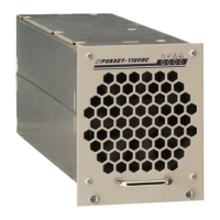
PSR327
User Manual
Page 11 (20)
©2009. ELTEK VALERE DEUTSCHLAND GmbH. UM_PSR327_21TE_ E_R5.0
4. Handling
4.1 Storage
Modules must be stored in a dry, dust free environment with a storage temperature in accordance with
the specific technical data (see section 8).
4.2 Commissioning
Note: Before commissioning the module, make sure that the input voltage corresponds to the input
voltage range of the unit as specified on the type plate and that the output voltage of paralleled units
matches.
1. Carefully unpack the unit
2. Fill the rack beginning with the left slot.
3. Put the unit into an empty slot.
4. Carefully slide in the unit until the module connector touched the backplane connector.
5. Increase the force until the unit fits in completely. Avoid using too much force. If the unit does not
fit in, begin again at step 3.
6. Secure the module using the two captive screws (M3x12) provided with the module.
7. Switch ON the module by external MCB.
Note: The PSR327 is serially equipped with an internal output side decoupling diode. This ensures
hot plug-in capability for the module and enables the operator to add modules under operating
conditions.
Note: Before a module is to be removed, it must be switched off by the external input fuse!
Caution: After switching off the module the internal capacitors are still fully charged. Do not touch
connector pins as they can still be charged with dangerous voltage after disconnection.
4.2.1 Start-up behavior
When the PSR327 is switched on (without CAN-Bus connection) first it provides a start-up voltage
according to the table below. The start-up voltage is held for 60 seconds, than the output voltage steps
up to the internal default value.
PSR327 48V version 60V version 110V version 220V version
Start-up voltage (VDC) 45.0 55.5 97.5 192.0
Default value Vo (VDC) 54.5 68.1 122.6 245.2
If a DC controller unit (UPC3) is integrated into the system, it is powered with the start-up voltage after
the rectifier has been switched on. The output voltage immediately steps up to the value given from the
UPC3 unit via CAN-Bus.
If a DC controller unit (UPC3) is integrated into the system (e.g. powered by the battery and due to this
operating yet) the rectifier directly provides the output voltage given from the UPC3 unit via CAN-Bus.
 Loading...