Rectifier
PSR327
User Manual
Page 9 (20)
©2009. ELTEK VALERE DEUTSCHLAND GmbH. UM_PSR327_21TE_ E_R5.0
3.4 Rear Side Connection
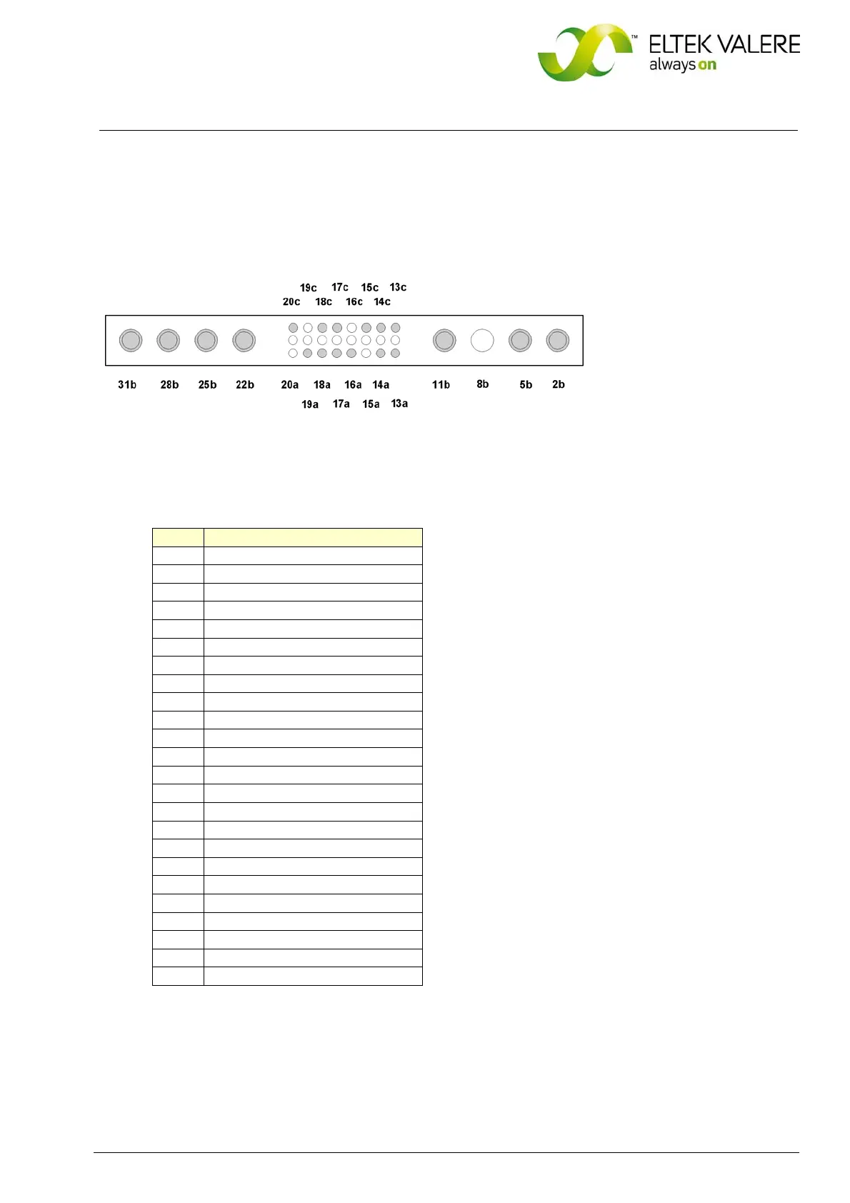
The rear side male connections (AC input voltage, DC output voltage and signals) are shown in figure 4)
and are defined in the table below.
Figure 4) Male connectors (shown from the rear side of the module)
Pin assignment of the rear side connector:
Pin Function
2b L1 - Input
5b N - Input
8b - - -
11b PE
13a CAN - CVSS
13c (-) output voltage sense link
14a CAN - H
14c CAN - L
15a - - -
15c CAN - CVCC
16a AGND
16c - - -
17a Hardwarecoding CODE2
17c Hardwarecoding CODE1
18a Collective Alarm NC
18c Collective Alarm COM
19a Collective Alarm NO
19c - - -
20a - - -
20c (+) output voltage sense link
22b (-) Output
25b (-) Output
28b (+) Output
31b (+) Output
 Loading...