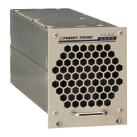
Rectifier
PSR327
User Manual
Page 4 (20)
©2009. ELTEK VALERE DEUTSCHLAND GmbH. UM_PSR327_21TE_ E_R5.0
Table of Contents
1. Safety Instructions and Waste Disposal Rules ........................................................................5
2. General Information ........................................................................................................................6
3. Type Range/Equipment.................................................................................................................6
3.1 Main Data .....................................................................................................................................................................6
3.2 Available Options and Assembly Equipment.......................................................................................................7
3.3 Front view/Front side LED panel ............................................................................................................................8
3.4 Rear Side Connection ................................................................................................................................................9
3.5 Cooling and Air Flow Direction.............................................................................................................................. 10
3.6 Communication Interface...................................................................................................................................... 10
4. Handling ..........................................................................................................................................
11
4.1 Storage ...................................................................................................................................................................... 11
4.2 Commissioning......................................................................................................................................................... 11
4.2.1 Start-up behavior ............................................................................................................................................. 11
4.3 Charge Characteristic/Output Power Diagram ...............................................................................................12
4.4 LED Indications......................................................................................................................................................... 13
4.5 Internal Monitoring.................................................................................................................................................. 13
4.6 Threshold & Default Values..................................................................................................................................14
4.7 Default value setting for NiCd batteries ........................................................................................................... 14
5. External Functions........................................................................................................................ 15
6. Maintenance .................................................................................................................................. 15
7. Troubleshooting............................................................................................................................ 16
8. Technical Specifications ............................................................................................................. 17
8.1 Dimensional Drawings............................................................................................................................................ 19
Index of Figures
Figure 1) DC Power Rack DCR PSR327-8.1 ....................................................................................................................7
Figure 2) DC Power Rack DCR PSR327-10.8..................................................................................................................7
Figure 3) Front view..............................................................................................................................................................8
Figure 4) Male connectors..................................................................................................................................................9
Figure 5) Module air flow.................................................................................................................................................. 10
Figure 6) Output power diagram (example PSR327/48-56)................................................................................... 12
Figure 7) Screenshot “Special software for CAN-Dongle”....................................................................................... 14
Figure 8) Module dimensions .......................................................................................................................................... 19

 Loading...