Rectifier
PSR327
User Manual
Page 14 (20)
©2009. ELTEK VALERE DEUTSCHLAND GmbH. UM_PSR327_21TE_ E_R5.0
4.6 Threshold & Default Values
The following table shows the factory set threshold/default values internally stored in the PSR327 unit
(for lead acid batteries):
Default values 48V version 60V version 110V version 220V version
Output voltage Vo (VDC) 54.5 68.1 122.6 245.2
Over voltage V> (VDC) 60.0 75.0 135.0 270.0
Current limiting Iconst (ADC) 56.0 45.0 25.0 12.5
Note: The threshold/default values can only be changed in combination with a UPC3 DC controller unit.
If an UPC3 DC controller unit is controlling the power supply unit through the CAN-Bus, the charge
voltage is completely controlled by the UPC3 based on its configuration values and momentary charge
state (for example temperature compensation, boost charge, or battery test). That means that the
values sent from the UPC over CAN-Bus have top priority. During CAN-Bus communication the internally
stored values of the rectifier are invalid.
But when the CAN-Bus connection is inactive for more than five seconds (e. g. due to trouble), the
PSR327 automatically switches back to the internally stored default values. In this case it is ensured
that the battery is charged in the float charge mode.
4.7 Default value setting for NiCd batteries
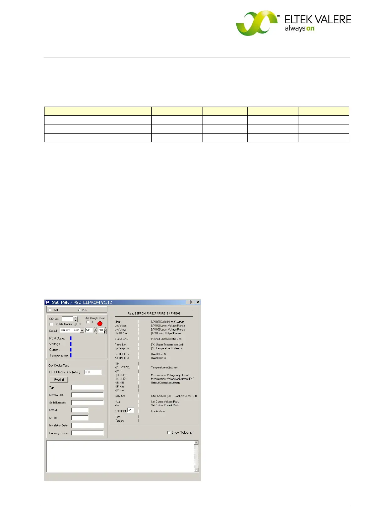
If the rectifier is to be used to charge NiCd batteries the default/threshold values must be set according
to the individual battery type using a CAN dongle and special software (see section 3.2 “Available
Options and Assembly Equipment”). A specific manual is available on request. For the adjusting range of
the output voltage please see section 8 “Technical Specifications”.
Figure 7) Scre
enshot “Special software for CAN-Dongle”
 Loading...