ESR series routers 11
ESR-100 and ESR-200 light indication
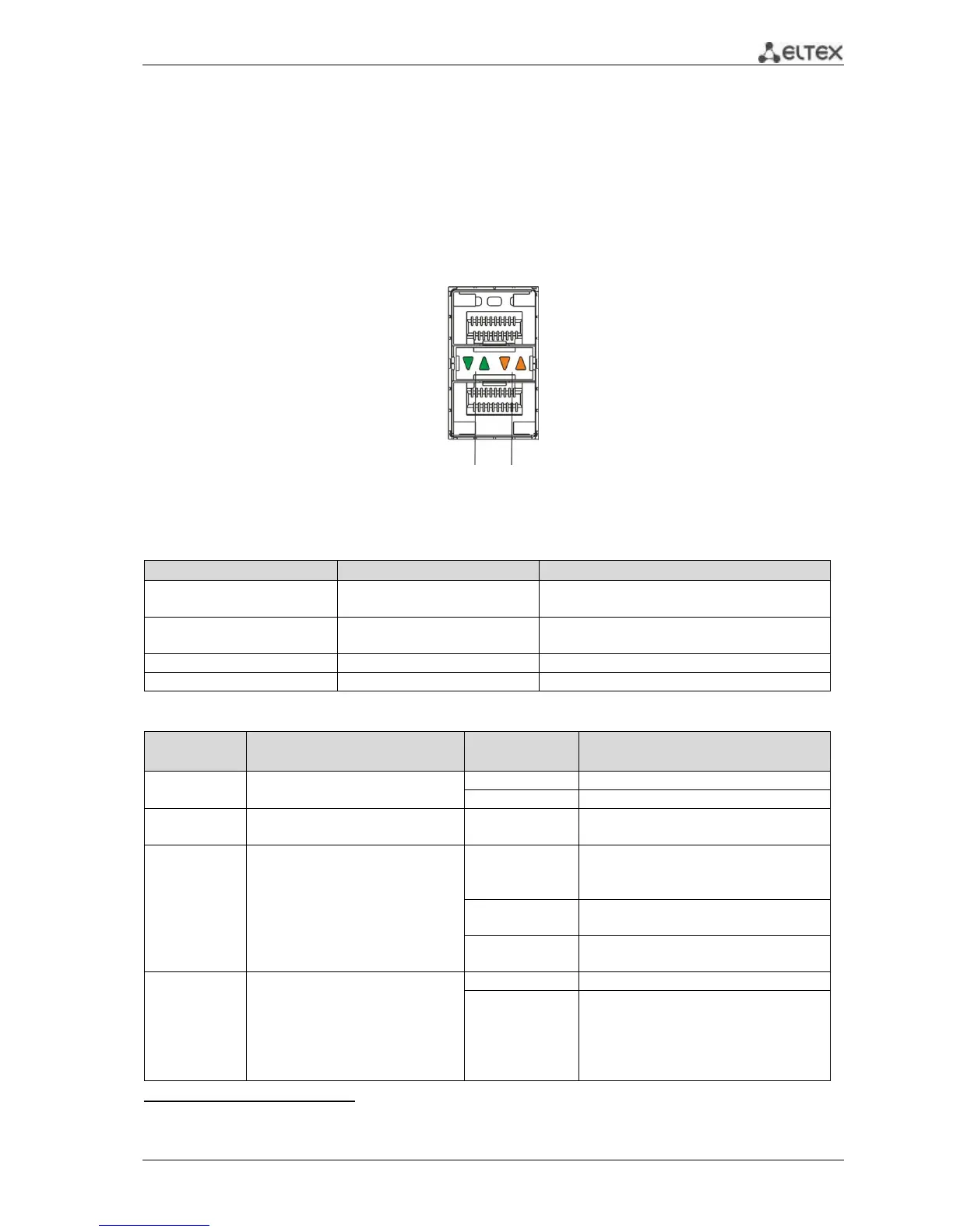
Metal interface states of GigabitEthernet and SFP-interfaces are represented by two LED indicators:
LINK/ACT - green and SPEED - amber. Location of cooper interfaces indicators is depicted in the Figure
2.11. Location of SFP interfaces indicators is depicted in the Figure 2.13. Description of light indication is
represented in the Table 2.9.
Figure 2.13 - Socket appearance with SFP-transceiver
Table 2.9 - Light state indication of metal interfaces and SFP- interfaces
LINK/ACT indicator is lit
Ethernet interface status
Port is disabled or connection is not
established
10Mbps or 100Mbps connection is
established
1000Mbps connection is established
Data transfer is in progress
Table 2.10 - System indicator states
Currency device indicator.
Device operates properly.
Device in software loading state.
Existence and device emergency
level indicator.
1
Device power supply is proper. Primary
power supply, if it is installed, operates
properly.
Disability of the primary power supply,
primary network fault or default.
Breakdown of the device internal
power supplies.
Emergency indicator of fans.
All the ventilators are fault free.
Breakdown of one or more ventilators.
The cause of the emergency can be
disability at least one of the ventilator
(for example, stopping or under-
frequency rotation).
1
It is not supported in the current software version.

 Loading...
