EasyManuals Logo

ELTEX NTU-1 User Manual

Default Icon
18 pages
To Next Page IconTo Next Page
To Previous Page IconTo Previous Page
Page #9 background imageLoading...
Page #9 background image
____________________________________________________________________________________
____________________________________________________________________________________
NTU-1 Optical Network Terminals 9
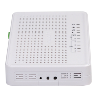
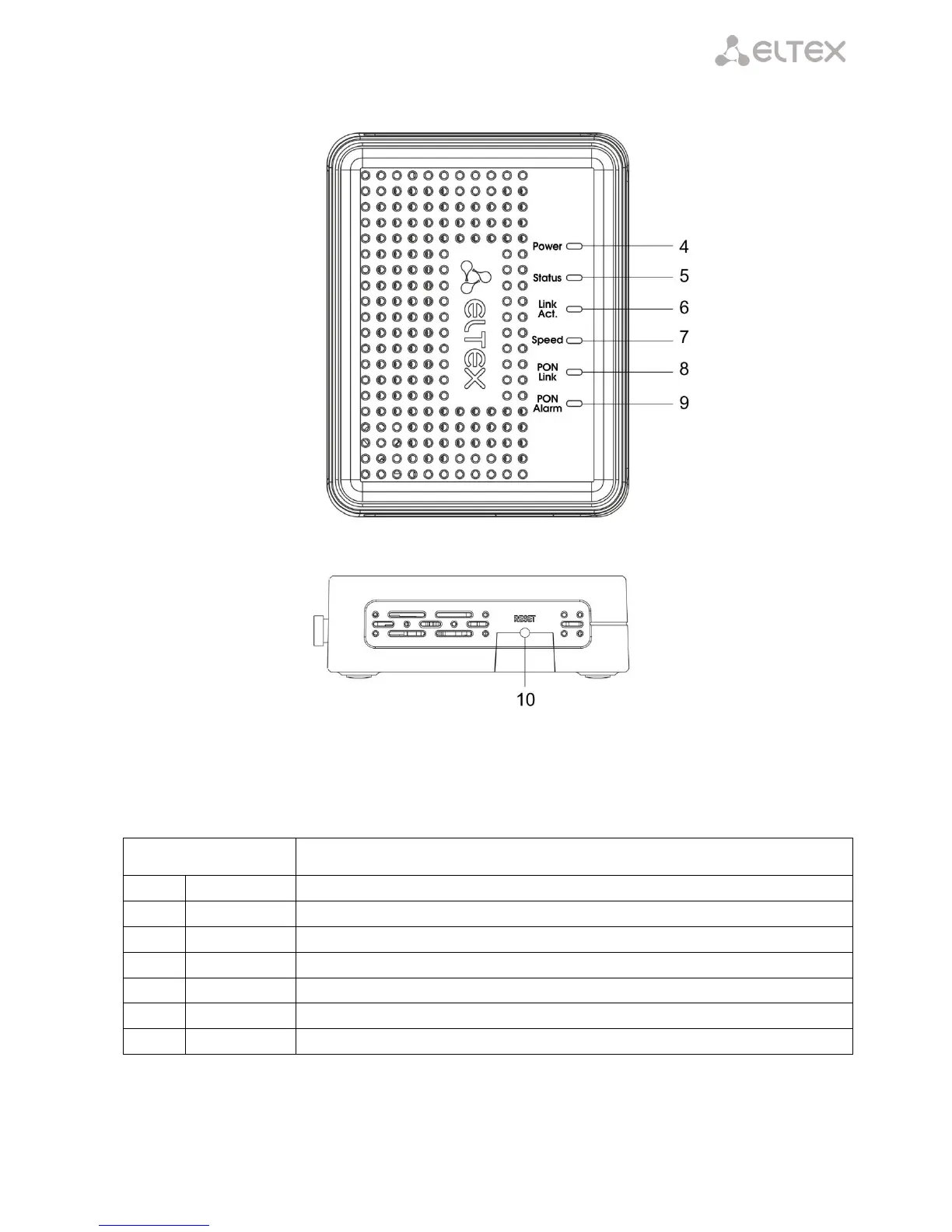
Fig. 3 shows a NTU-1 side and top panels.
Fig. 3 NTU-1 Top and Side Panel
Controls and LED indicators located on the NTU-1 side and top panels are listed in Table 4.
Table 4 Description of LEDs and Controls Located on the Side and Top Panels
Panel Element
Description
4
Power
power on indicator
5
Status
device authentication indicator
6
Link Act.
Ethernet ports indicator
7
Speed
Ethernet-port connection speed indicator
8
PON Link
optical interface indicator
9
PON Alarm
connection with the station indicator optical terminal
10
Reset
a functional key that reboots the device and resets it to factory settings

Questions and Answers:

Question and Answer IconNeed help?

Do you have a question about the ELTEX NTU-1 and is the answer not in the manual?

ELTEX NTU-1 Specifications

General IconGeneral
BrandELTEX
ModelNTU-1
CategoryTouch terminals
LanguageEnglish

Related product manuals