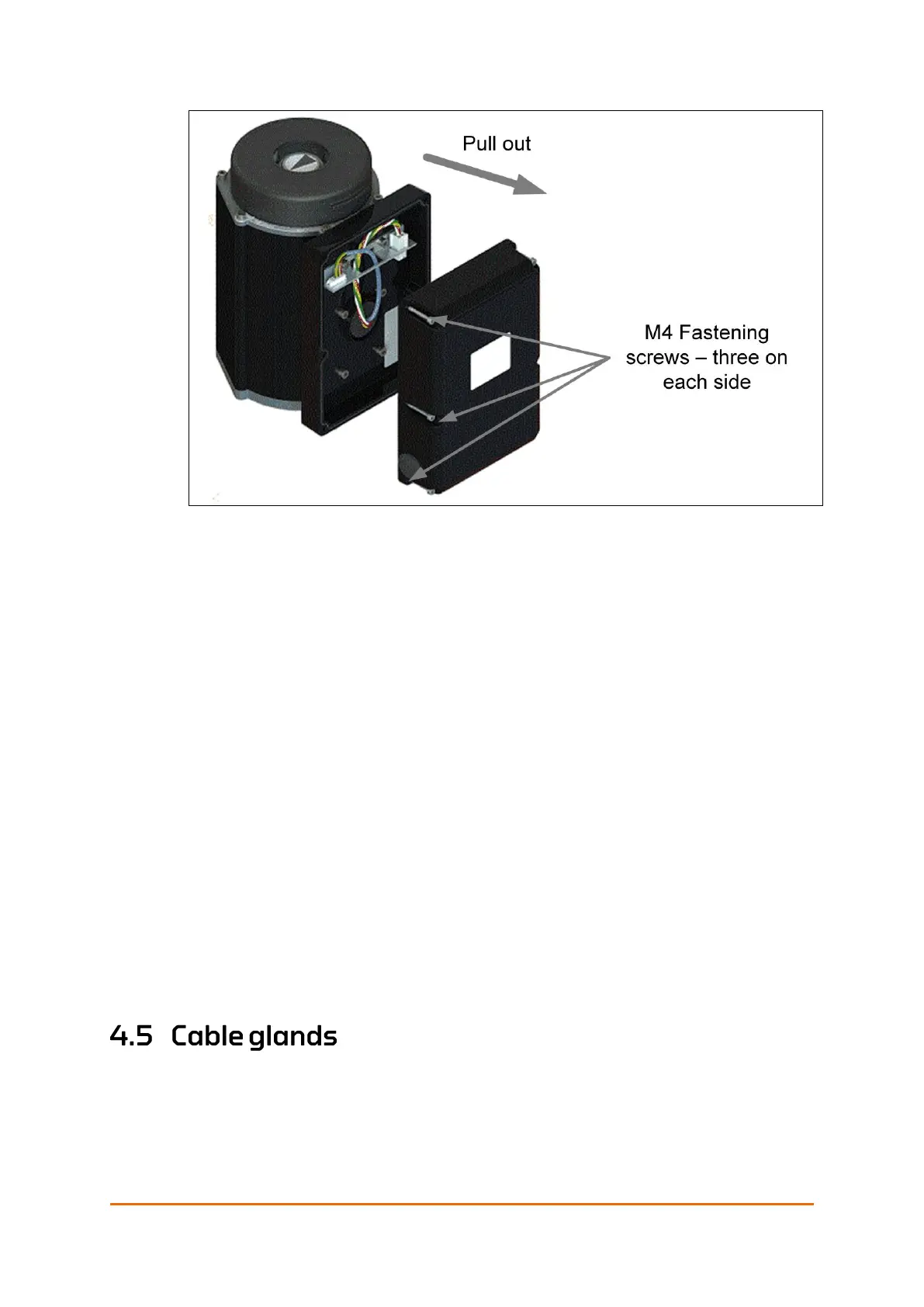
Figure 22: Removing the communication interface box
1. Loosen the six fastening screws (three on each side) on the
communication interface box, see Figure 22 above.
2. Remove the box by pulling it straight out.
3. Install the required cable glands, see section 4.5.
4. Strip all wire-ends to 8 – 9 mm/0.31 – 0.35 in.
5. Install the power supply cables through the cable glands on the right side
and connect them to the L, N and G/ PE terminals, see section 4.6.
6. Install the control signal cables through the cable glands on the left and
connect them according to the type of communication interface box used
in the installation. See section 4.8.
7. Connect the configuration medium to X2 configuration connector if
applicable.
Note! When re-assembling the communication interface box with the actuator, make
sure that no wires are jammed between the surfaces and that the screws are
cross-tightened. It is also recommended to apply some seal lubrication on the
gasket to ensure that the actuator remains water proof.
8. Replace the box and tighten the fastening screws to the specified torque.
See Table 22: Screw torque on page 81. Also see the note above.
For trouble-free operation, it is important to install the glands and cable
correctly. Eltorque’s IP certification may be voided if the instructions of the
glands are not followed.
Note! Support the cable to prevent it from twisting
• Ensure that the correct cable and gland are at hand.
 Loading...
