Page 5
List of figures
Figure 1 The AIS network ................................................................................................................. 9
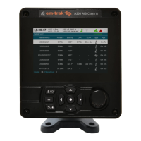
Figure 2 Transceiver front panel ..................................................................................................... 11
Figure 3 Display layout ................................................................................................................... 12
Figure 4 Selection of main operating screen .................................................................................. 13
Figure 5 Target list screen and vessel details view ........................................................................ 14
Figure 6 Own vessel and voyage data screen................................................................................ 14
Figure 7 Own dynamic data screen ................................................................................................ 15
Figure 8 Received messages screen.............................................................................................. 16
Figure 9 Message details view........................................................................................................ 16
Figure 10 Alarms screen................................................................................................................... 17
Figure 11 Alarm details view............................................................................................................. 17
Figure 12 Target plot screen............................................................................................................. 18
Figure 13 Target plot symbols .......................................................................................................... 18
Figure 14 Safety Related Message notification ................................................................................ 19
Figure 15 Message composition ....................................................................................................... 19
Figure 16 Alarm notification screen .................................................................................................. 20
Figure 17 Text entry.......................................................................................................................... 22
Figure 18 Long range interrogation notification; automatic response mode enabled ....................... 23
Figure 19 Long range interrogation notification; manual response mode enabled........................... 23
Figure 20 Long range message list and details views ...................................................................... 23
Figure 21 Password entry screen ..................................................................................................... 24
Figure 22 Main menu structure......................................................................................................... 25
Figure 23 Main menu screen ............................................................................................................ 26
Figure 24 The voyage data menu..................................................................................................... 26
Figure 25 The messages menu ........................................................................................................ 27
Figure 26 The user settings menu .................................................................................................... 27
Figure 27 The installation menu........................................................................................................ 28
Figure 28 The maintenance menu.................................................................................................... 28
Figure 29 Diagnostics menu ............................................................................................................. 29
Figure 30 Tanker mode entry acknowledgement screen.................................................................. 29
Figure 31 Tanker mode exit screen when speed exceeds 3 knots................................................... 30
Figure 32 Typical AIS transceiver connection................................................................................... 33
Figure 33 What’s in the box .............................................................................................................. 34
Figure 34 AIS transceiver dimensions .............................................................................................. 36
Figure 35 Mounting the AIS transceiver............................................................................................ 36
Figure 36 Panel mounting the AIS transceiver ................................................................................. 37
Figure 37 Junction box dimensions .................................................................................................. 38
Figure 38 Mounting the junction box................................................................................................. 38
Figure 39 GPS antenna location....................................................................................................... 39
Figure 40 GPS antenna connection.................................................................................................. 39
Figure 41 VHF antenna installation................................................................................................... 40
Figure 42 VHF antenna connection .................................................................................................. 41
Figure 43 Connecting the junction box to the transceiver................................................................. 41
Figure 44 Junction box connections ................................................................................................. 43
Figure 45 Example connection to external display equipment.......................................................... 45
Figure 46 Line termination options.................................................................................................... 45
Figure 47 Power connection ............................................................................................................. 46
Figure 48 PC data (RS232) connection ............................................................................................ 47
Figure 49 Vessel dimensions measurement..................................................................................... 49
Figure 50 Regional areas list screen ................................................................................................ 51
Figure 51 Regional area editing screen............................................................................................ 52
Figure 52 Regional area settings confirmation screen...................................................................... 52
Figure 53 Blue sign switch connection.............................................................................................. 55
Figure 54 Input port schematic ......................................................................................................... 62
 Loading...