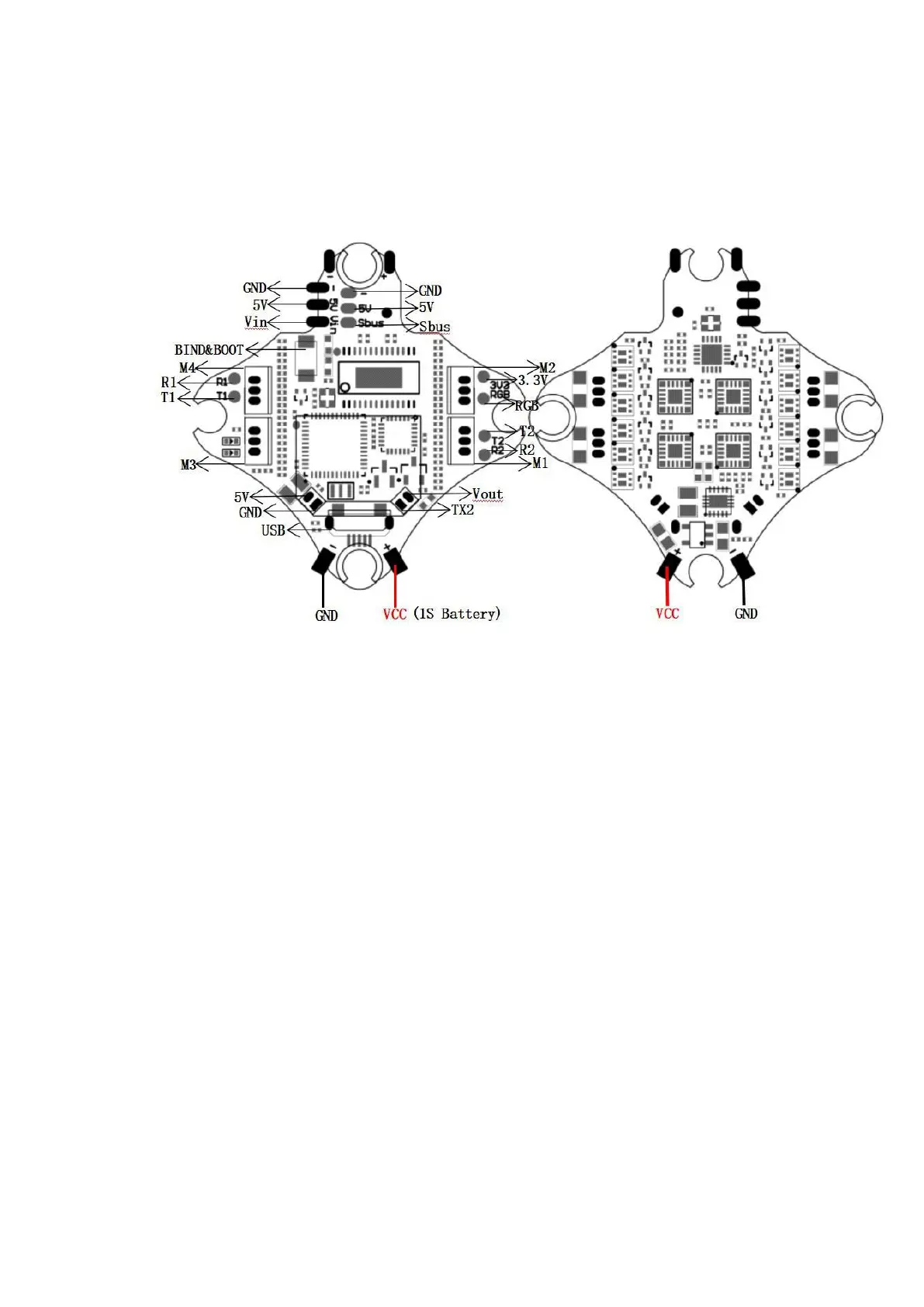
6. Tinyhawk III Flight Control Diagram
6.1 Tinyhawk III Flight Control Diagram
This flight controller has a MCU(STM32F411CEU6) with a MPU6000 gyro.
Tinyhawk III flight controller comes pre-programmed and properly tuned for optimal flight.
For a full tune and configuration setting file (CLI dump file) please visit https://emax-
usa.com/ for the CLI dump file.
6.2 Stock Flight Controller Settings
Tinyhawk III is configured to TAER1\2\3\4 Channel Mapping.
E8 Transmitter is used in the example below:
AUX 1 is a 3-level switch to select the flight mode; Acro, Horizon and Angle are activated
in increasing order. The unlock switch of Tinyhawk III is set on AUX 1, and the highest
value.
AUX 2 is configured as a buzzer. In the high level state, the motor will emit a beep. The
auxiliary device 4 is set to a post-collision rollover mode (usually referred to as "turtle
mode").
AUX 3 is configured as a buzzer to facilitate finding the position of the aircraft
AUX 4 is configured as a buzzer turtle mode. AUX 4 is set in a high state in the following
situations. Configure your E8 Transmitter as described above, or change these settings in
the Betaflight Configurator.