EMC® VNX5300™ Hardware Information Guide
84
EMC® VNX5300™ Hardware Information Guide
Interleaved cabling
in a VNX5300
File/Unified platform
with seven DAEs
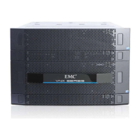
Figure 75 on page 85 shows an example of a VNX5300 File/Unified platform with
seven DAEs (all are 3U, 15 disk drive DAEs) or a VNX5300 File/Unified platform
with a total of 120 disk drives (with the DPE a 3U, 15 disk drive device).
In this example, the SAS ports on the VNX5300 platform DPE are labeled 0 and 1.
SAS 0 is connected internally to the SAS expander that connects to the internal DPE
disks. However, since there are seven DAEs for a maximum of 120 disk drives, it is
recommended that the DAEs be load balanced. To do this, it is recommended that
you daisy chain the DAEs for the most efficient load balancing. So, in Figure 75 on
page 85, there are two buses (Bus 0 and Bus 1) with the first DAE on Bus 1 designated
as EA0/Bus 1 (blue cable). The second DAE continues Bus 0 and is designated as
EA1/Bus 0 (orange cable) where it is then daisy-chained to the fourth DAE
designated as EA2/Bus 0 and then to the sixth DAE designated as EA3/Bus 0, and so
on.
The cables shown in Figure 75 on page 85 are:
Note: The cable colors shown in the example are orange for Bus 0 and blue for Bus 1.
◆ Cable 1, blue, DPE to 1
st
DAE (labels SP A SAS 1 to LCC A)
◆ Cable 2, blue, DPE to 1
st
DAE (labels SP B SAS 1 to LCC B)
◆ Cable 3, orange, DPE to 2
nd
DAE (labels SP A SAS 0 to LCC A)
◆ Cable 4, orange, DPE to 2
nd
DAE (labels SP B SAS 0 to LCC B)
The remaining cables are daisy-chained for load balancing. So, the blue cable for Bus
1 is interleaved and daisy-chained through the remaining DAEs:
◆ EA 1/Bus 1
◆ EA 2/Bus 1
◆ EA 3/Bus 1
While the orange cable for Bus 0 is interleaved and daisy-chained through the
remaining DAEs:
◆ EA 2/Bus 0
◆ EA 3/Bus 0
Note: In Figure 75 on page 85 the VNX5300 File platform shows an dual SPS, a DPE (with two
SPs), two CSs, a DME (with two DMs), and seven 3U 15 DAEs.

 Loading...