6 Chapter 1 Introduction
LCU+ Series Controller User Manual
individually. There is one reconnection level for all LVDs. These LVDs can be used for load disconnection
and/or battery disconnection.
LVD Disconnection Setting Precautions
(1) The disconnection level for load contactor should be set higher than the battery contactor so that the load
contactor can always be disconnected before the battery contactor.
(2) Maximum 1 LVD is used for battery disconnection to protect from the large current difference between
batteries (using the internal LVD2 of the controller is suggested). When Commercial AC returns, the batteries
can be close to complete discharge and the voltage difference can generate a large current. Therefore, the
current of rectifiers should be limited before the battery reconnection.
The controller can individually disable LVD1 and LVD2, preventing the contactor from opening during an LVD
condition.
The controller can reconnect the LVDs when the Commercial AC Fault alarm is inactive and system voltage is
higher than the reconnection level.
An LVD alarm is issued when the controller automatically or a User through the controller manually activates an
LVD. An LVD Detection Fault alarm is also issued when the controller detects the auxiliary input status is not
identical with the LVD operation.
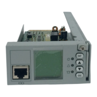
1.4 Hardware Interfaces
1.4.1 I/O Connector Of Motherboard
This connector is located at the lower rear part of the controller. It is a 50 PIN PCB golden finger connector. For
connector pin-outs, refer to Appendix 1 Hardware Interfaces.
1.4.2 RS232 Interface
This connector is located in the left lower part on the controller front panel and it is an RJ45 connector.
Table 1-8 RS232 Connector
1.4.3 Ethernet Port
This connector is located in the left upper part on the controller front panel and it is an RJ45 connector.
Table 1-9 Definition of Ethernet Port
 Loading...