Chapter 1 Introduction 3
LCU+ Series Controller User Manual
Weight: <1kg
1.3 Main Functions
1.3.1 Measurement Functions:
Analog value measurement
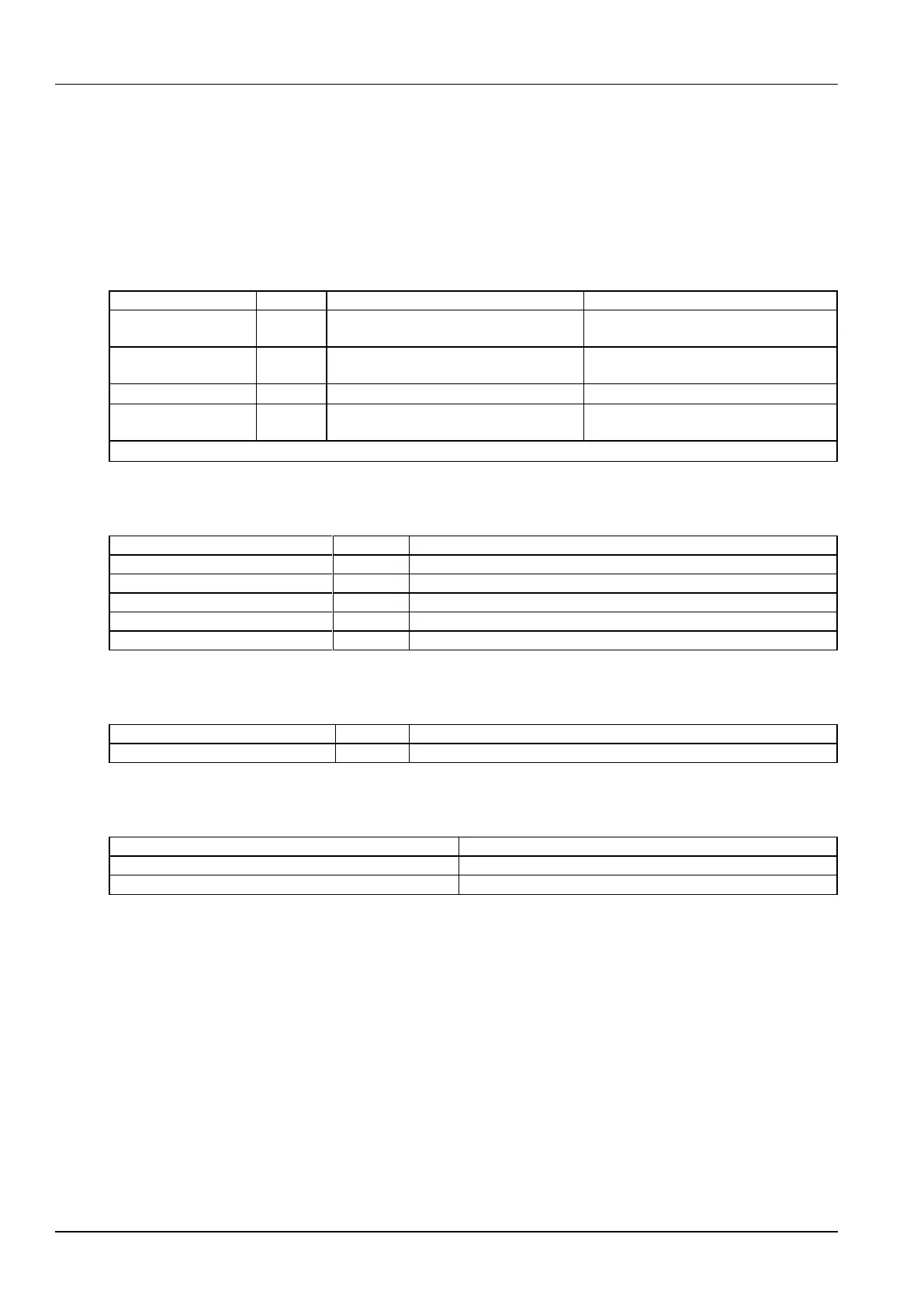
Table 1-4 Analog value measurement
Differential Voltage Signal of Battery Shunt:
-100mV ~ 100mV
Error is less than ±1% of full measurement
range
-48V System: 10Vdc ~ 65Vdc.
+24V System: -10Vdc ~ -30Vdc
± 0.1V, absolute value is 19V to 60V
233uA to 373uA (-40
C ~ 100
C)
± 2
C (sensor error is not considered)
-48V System: 10Vdc ~ 65Vdc.
+24V System: -10Vdc ~ -30Vdc
± 0.2V, absolute value is 19V to 60V
Note: The applicable scope of all the measurement resolution is 15
C ~ 30
C
Digital value measurement
Table 1-5 Digital value measurement
Absolute Value: 15V ~ 60V fault, 0 to 1V normal.
Absolute Value: < 400mV - 50mV normal, > 400mV + 50mV fault.
DI for Status of bi-stable contactor
Absolute Value: 15V ~ 60V open, 0V ~ 1V close.
DI for Auxiliary Contact of SPD
Expansion board needs to be connected
Digital output
Table 1-6 Digital output
Capacity of Contact: 1A / 30Vdc or 125Vac, expansion board is needed
Power output
Table 1-7 Power Output
Power Out of External Interface Board
Power Out of Temperature Sensor
LVD drive
The controller has 2 LVD drive outputs that can drive two bi-stable / mono-stable contactors.
1. Bi-stable Contactor: 2A maximum drive current with drive pulse width of 500ms ~ 1s.
2. Mono-stable Contactor: 3A maximum starting current and 1A maximum holding current.
1.3.2 Display And Indicating Functions
The controller has a green LED for indicating operating status, a yellow LED for indicating observation alarm, and a
red LED for indicating major and critical alarms. It also provides a drive output for alarm LED on a system cabinet.
The controller LCD can display the AC parameters, DC parameters, rectifier and battery parameters, operating status,
alarm status, settings, and control parameters.
 Loading...