16 Chapter 3 Operation
LCU+ Series Controller User Manual
DI SETTINGS
All the alarms can be configured with No.1 to No.8 alarm contacts. ‘0’ means no alarm dry contacts. All the alarm dry
contacts provide NC (normally closed) or NO (normally opened) output and the default alarm dry contacts are given in
the following table.
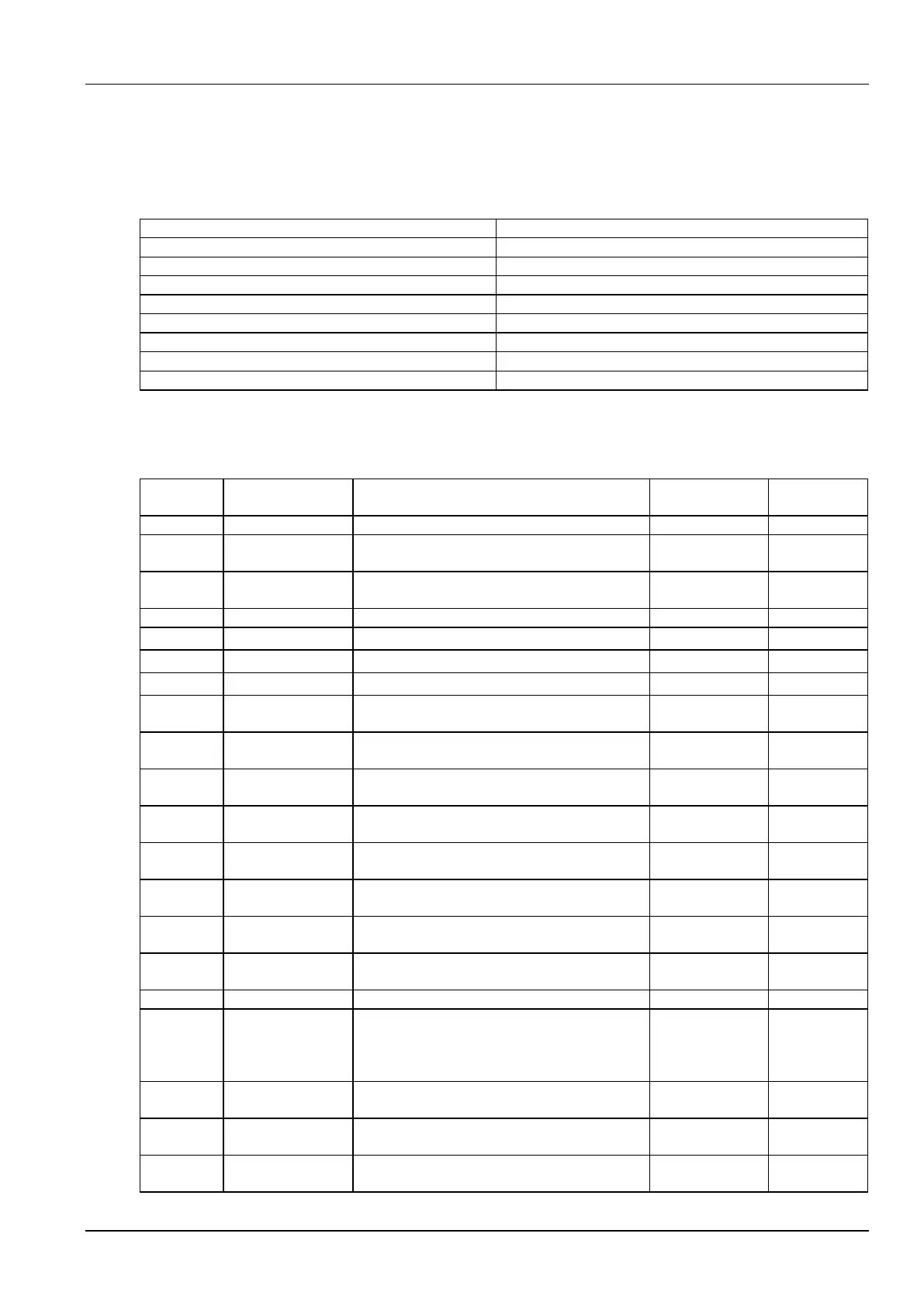
Table 3-4 Default alarm dry contact setting
DC Under Volt or DC Over Volt
Table 3-5 lists the alarms that you can scroll through in the ALARM SETTINGS/ALARM LEVEL menu, and also
shows their factory default ‘Alarm Level’ and ‘Mapped Output Relay’ settings.
Table 3-5 Controller Alarms and Factory Default Settings
Default mapped
output relay
Alarms are blocked by the LCU+
Battery middle voltage out of the range of ( bus
voltage /2) ± 0.6
Into and out of save power status for 5 times in one
hour
System is in save power status
Input phase voltage higher than AC High point
Input phase voltage lower than AC Low point
Ambient/ Battery temperature higher than
Temperature High 2
Ambient/ Battery temperature higher than normal
operation range
Ambient/ Battery temperature lower than normal
operation range
The charging current over the maximum value
System output voltage much higher than float
charge voltage
System output voltage higher than float charge
voltage
System output voltage slightly lower than float
charge voltage
System output voltage is much lower than float
charge voltage
Rectifier HVSD circuit activated
The difference between rectifier output current and
average output current larger than 8A (+/-4A), and
the load of the rectifier greater than 10% of its
capacity
The output power of at least one rectifier is derated
because of AC undervoltage or overtemperature
Fan of at least one rectifier fails
AC input voltage out of the range of 85Vac to
295Vac results in at least one rectifier protected
 Loading...