Menu 4 Introduction
Parameter
x.00
Parameter
description format
Keypad and
display
Serial
communications
CT Modbus
RTU
PLC Ladder
programming
CTSoft Menu 0
Advanced parameter
descriptions
68 Commander SK Advanced User Guide
www.controltechniques.com Issue Number: 9
The DC bus controller gain is a function of DC bus capacitance and therefore is fixed internally. It may often be necessary to adjust the current
controller gains to obtain the required performance. If the gains are not suitable it is best to set up the drive in torque control first. Set the gains to a
value that does not cause instability around the point at which field weakening occurs. Then revert back to open loop speed control in standard ramp
mode. To test the controller the supply should be removed while the motor is running. It is likely that the gains can be increased further if required
because the DC bus voltage controller has a stabilising effect, provided that the drive is not required to operate in torque control mode.
See Pr 4.16 for details.
0: OFF Trip when threshold reached
1: On Reduce current limit when threshold reached
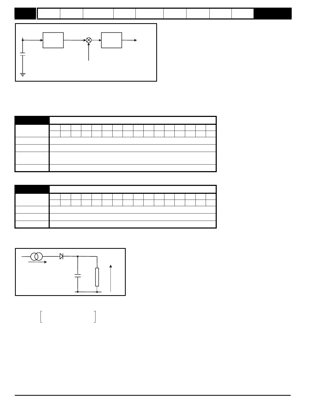
The motor is modelled thermally in a way that is equivalent to the electrical circuit shown below:
The temperature of the motor as a percentage of maximum temperature, with a constant current magnitude of I, constant value of K and constant
value of motor rated current (set by Pr 5.07 or Pr 21.07) after time t is given by
This assumes that the maximum allowed motor temperature is produced by K x Motor rated current and that τ is the thermal time constant of the point
in the motor that reaches it maximum allowed temperature first. τ is defined by Pr 4.15. The estimated motor temperature is given by Pr 4.19 as a
percentage of maximum temperature. If Pr 4.15 has a value of 0 the thermal time constant is taken as 1.
If the rated current (defined by Pr 5.07 or Pr 21.07 depending on which motor is selected) is less or equal to the Maximum heavy duty rating then
Pr 4.25 can be used to select 2 alternative protection characteristics (see diagram below). If Pr 4.25 is OFF(0) the characteristic is for a motor which
can operate at rated current over the whole speed range. Induction motors with this type of characteristic normally have forced cooling. If Pr 4.25 is
On(1) the characteristic is intended for motors where the cooling effect of motor fan reduces with reduced motor speed below half of rated speed. The
maximum value for K is 1.05, so that above the knee of the characteristics the motor can operate continuously up to 105% current.
Below the knee point, the drive will display OVL.d, with Pr 4.01 at 100% current.
4.15 Motor thermal time constant
Coding
Bit SP FI DE Txt VM DP ND RA NC NV PT US RW BU PS
111
Range 0 to 250 s
Default 89
Second motor
parameter
Pr 21.16
Update rate Background
4.16 Motor thermal protection mode
Coding
Bit SP FI DE Txt VM DP ND RA NC NV PT US RW BU PS
111
Range OFF(0) or On(1)
Default OFF(0)
Update rate Background
DC Bus
voltage
controller
P Pr
4.13
I Pr
4.14
Frequency
reference
Active current
DC Bus
capacitor
Current
demand
+
_
[(I /(K x Motor Rated Current)
22
]
=RCt
Temp
C
R
Temp
I
2
K Motor rated current×()
2
-------------------------------------------------------------------------
1e
-t τ⁄
–()100%×=