When using the single POD options, the UPS power cables should be connected through the user terminal block, UPS
terminal block and PE terminals of the single POD rear panel. The terminal distribution of each terminal block on
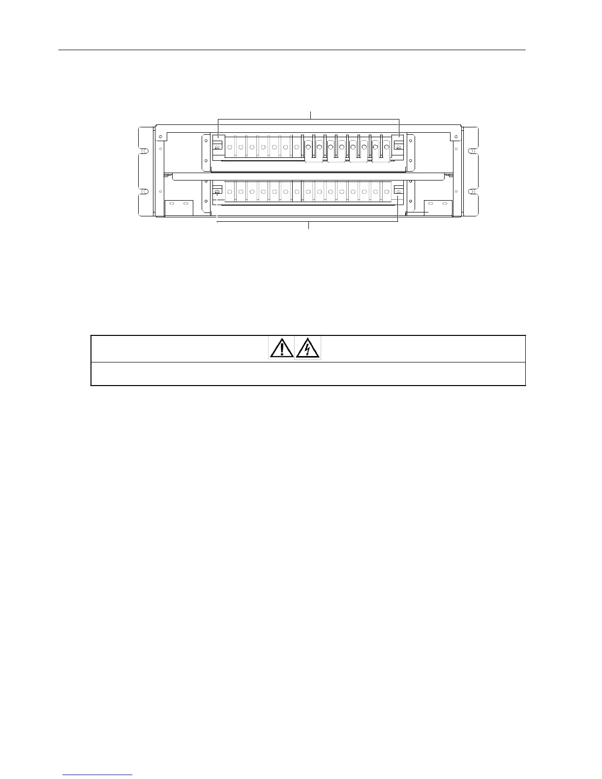
the POD rear panel and PE terminals are shown in Figure 2-8.
User terminal
block
oN oN oA oB oC
3 3 3 3
mN bN mA bA
mB
bB mC bC
PE PE
oN oN oA oB oC mN bN mA bA mB bB mC bC
PE PE
UPS terminal
block
Note: 1. Main input: mA, mB, mC, mN; Bypass input: bA, bB, bC, bN
Output: oA, oB, oC, oN; Battery: Bat +, Bat N, Bat -; GND: PE
2. In factory, four shorted copper bars 3 have been used to short terminals between mA and bA,
mB and bB, mC and bC, mN and bN respectively
Figure 2-8 Terminals distribution of the terminal blocks and PE terminals
The UPS I/O terminal block, the single POD user terminal block and UPS terminal block all have protective covers.
Before the connection, you should remove the protective cover of each terminal block; after the connection, you
should reinstall these protective covers.
Warning
After the cables connection, you must reinstall the protective cover of each terminal block, so as to avoid the electric shock when
the UPS is in operation state.
Single POD
options
(Re
c
o
mm
e
nd
e
d
)
•
3-in 3-out, common source configuration (factory default)
1. Connect the live line (input phase A, input phase B and input phase C), N line and PE line respectively to the user
terminal block (mA, mB, mC and mN terminals) and PE terminals of the single POD.
2. Connect the live line (output phase A, output phase B and output phase C), N line and PE line respectively to the
user terminal block (oA, oB, oC and oN terminals) and PE terminals of the single POD.
3. Remove all the shorted copper bars 3 from the UPS I/O terminal block, connect the UPS terminal block of the
single POD with the same silkprint terminal of the UPS I/O terminal block using one-to-one correspondence method,
and connect two PE terminals of the UPS I/O terminal block to the single POD PE terminals.
•
3-in 3-out, split-bypass configuration
1. Remove all the shorted copper bars 3 from the single POD user terminal block.
2. Connect the live line (mains phase A, mains phase B and mains phase C), N line and PE line respectively to the
user terminal block (mA, mB, mC and mN terminals) and PE terminals of the single POD.
3. Connect the live line (bypass phase A, bypass phase B and bypass phase C), N line and PE line respectively to
the single POD user terminal block (bA, bB, bC and bN terminals).
4. Connect the live line (output phase A, output phase B and output phase C) and N line respectively to the single
POD user terminal block (oA, oB, oC and oN terminals).
5. Remove all the shorted copper bars 3 from the UPS I/O terminal block, connect the UPS terminal block of the
single POD with the same silkprint terminal of the UPS I/O terminal block using one-to-one correspondence method,
and connect two PE terminals of the UPS I/O terminal block to the single POD PE terminals.