Do you have a question about the Emerson Bettis RTS and is the answer not in the manual?
Summarizes WARNING, CAUTION, and NOTE notices for personal safety and equipment protection.
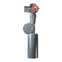
Introduces the PROFINET bus system interface for Bettis RTS electric actuators as a hardware option.
Details supported network structures like line, tree, star, and mixed forms for PROFINET.
Lists key technical data including data capacity, cycle time, baud rate, and transport layer.
Outlines limitations and unsupported features for the PROFINET interface.
Explains the M12 connector setup for standard PROFINET fieldbus connections.
Details wiring via screw terminals and shielding clamps for explosion-proof units.
Explains IOPS (Provider State) and IOCS (Consumer State) for data validity and handling.
Lists additional parameters for configuration when the PROFINET option is enabled.
Covers position assignment, commands, and set points for data transfer from master to slave.
Details extended registers for executing commands and reading/writing values.
Describes actual position, status, torque, and speed data transmitted from slave to master.
Explains message status bits for transaction execution, errors, and busy states.
The Bettis RTS is an electric actuator designed for connectivity with PROFINET bus systems, an IEEE 802 Ethernet-based fieldbus system. This PROFINET interface is a hardware option that must be specified when ordering the actuator.
The Bettis RTS actuator, when equipped with the PROFINET interface, integrates into a PROFINET IO network, utilizing a cyclic process data image for communication. Both the PROFINET IO Controller and Device maintain an image of input and output data, which is updated periodically via Ethernet frames. These frames contain I/O data and associated data status, configured at intervals by an engineering tool. The system operates on a Provider Consumer model, where an I/O data consumer exists for every I/O data provider, and both communicate their current state through various frames. These states include the IO Provider State (IOPS), indicating whether the associated data is valid (good) or invalid (bad), and the IO Consumer State (IOCS), which the consumer returns to the provider to indicate if the data has been handled. Each submodule within the PROFINET IO system exchanges its I/O data and two I/O data states with the IO-Controller.
The actuator supports various commands and data exchanges over the PROFINET network. Set points for position can be written and read, and commands such as OPEN, CLOSE, STOP, EMERGENCY OPEN/CLOSE, BLOCK, POSITIONER OFF, and WATCHDOG can be issued. Latched Open/Close commands, locking functions, and fail-safe triggers are also supported. Additionally, the system allows for intermediate position commands and PVST (Process Value Status) start.
Extended registers enable the execution of further commands and the reading of various information. This involves specifying a register number and, if applicable, a value to be written or read. The system also provides output data from the slave (actuator) to the master (controller), including actual position, status information, actual torque, actual speed, and external actual value (for PID-controller option).
Status information includes:
| Brand | Emerson |
|---|---|
| Model | Bettis RTS |
| Category | Recording Equipment |
| Language | English |