EasyManua.ls Logo

Emerson Bettis 500 User Manual

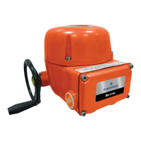
Emerson Bettis 500
102 pages
To Next Page IconTo Next Page
Page #1 background imageLoading...
Page #1 background image
Installation and Operation Manual
E2K-405-0218 Rev. 2
February 2018
TEC2 Electric Actuator with Model 500

Table of Contents

Questions and Answers:

Emerson Bettis 500 Specifications

General IconGeneral
BrandEmerson
ModelBettis 500
CategoryController
Housing MaterialAluminum
Model Series500 Series
Control Signal4-20 mA
Enclosure RatingIP66
Communication ProtocolHART
Operating Temperature-40°C to 85°C

Summary

Section 1: Important Notes

User Safety

Safety notices detail precautions to reduce risk of personal injury and equipment damage.

Purpose

Explains how to install, operate, and maintain the TEC2 valve actuator.

Storage Procedures

Procedures to ensure optimum performance when the actuator cannot be installed immediately.

Section 2: Quick Start

Set Position Limits

Step-by-step instructions for initializing the TEC2 actuator's position limits.

Network Setup

Configuration steps for the Communication Adapter Module (CAM).

Check Settings

Verifies correct operation and display readings after setup.

Section 3: Installation

Preparing the Stem Nut

Instructions for preparing the stem nut for actuator mounting.

Mechanical Installation onto the Valve

Detailed steps for physically mounting the actuator onto the valve.

Electrical Connections

Procedures for making electrical connections to the actuator.

Remove Separate Terminal Chamber (STC) Cover

Step to remove the cover of the Separate Terminal Chamber.

Sealing Cable/Conduit Entries

Guidelines for sealing cable and conduit entries according to codes.

Recommended Terminal Connections

Best practices for making terminal connections using wire binding screws.

Cable Connections

Specific instructions for connecting power and control wires.

Replace Terminal Compartment Cover

Steps to reinstall the terminal compartment cover.

External Earth/Ground Connections

How to connect external earth/ground to the actuator.

Display Backup Module (DBM) – Optional

Details on the optional battery pack for electronics power.

Discrete Controlled Inputs

Connecting discrete inputs for actuator control.

Auxiliary Control Module (ACM) – Optional

Expanding actuator functionality with optional ACM modules.

Wiring the ACM

Instructions for wiring the Auxiliary Control Module.

Analog Controlled – Power Supply Connections

Connecting power supplies for analog controlled inputs/outputs.

Network Controlled

Setting up network control with ACM and CAM.

Auxiliary Relay Module (ARM) Wiring

Wiring instructions for the Auxiliary Relay Module.

Remote Display Module (RDM) Connection to the Actuator – Optional

Connecting the Remote Display Module to the actuator.

24 Vdc Power Source

Connecting RDM to a 24 Vdc power source.

115/230 Vac Power Source

Connecting RDM to an external AC power source.

Two RDMs (One 24 Vdc and One 115/208/220/230 Vac Power Source)

Using two RDMs with different power sources.

RDM Connections and Dip Switch Settings

Configuring RDM connections using dip switches.

Section 4: Operation

Local Display Module

Overview of the Local Display Module and its components.

Graphics Display and Message Center

Functionality of the graphics display and message center.

Control Knob and Selector Knob

Operation of the control and selector knobs for navigation and input.

LEDs

Description of the status indicator LEDs on the LDM.

Normal Display Function

How the display indicates normal valve activity.

Remote Display Module (RDM)

Overview of the Remote Display Module functions.

RDM Operation with LDM

Priority of operation between RDMs and LDM.

Initializing the Actuator

Steps to initialize the actuator before operation.

Setting Position Limits

Procedures for setting the valve's open and close position limits.

View Existing Settings

How to check the actuator's default configuration settings.

Local Control Operation

How to control the actuator locally using LDM or RDM.

Remote/Auto Control Operation

Controlling the actuator via discrete inputs or other remote modes.

Section 5: Customizing Actuator Settings

Entering Setup Mode

How to access the actuator's setup menu for configuration.

Setting Limits

Bypasses initial limit setting and refers to modification options.

Changing Display

Options for changing language and contrast settings.

Displaying Unit Parameters

Viewing various actuator parameters like tag name, model, etc.

Change Settings

Accessing and changing various actuator configuration settings.

Passcode Entry

Procedure for entering the existing passcode to change settings.

Valve Control Setup

Configuring the valve control mode and related settings.

Set Valve Travel Limits

Adjusting or re-setting valve travel limits.

Discrete Input Setup

Configuring the discrete inputs for remote control.

Discrete Output Setup

Configuring relay outputs for status feedback.

Inhibit and ESD Setup

Configuring control inhibits and emergency shut down settings.

Two-Speed Timer Setup

Configuring timers for two-speed operation.

Analog Setup (ACM Required)

Configuring analog inputs/outputs when ACM is installed.

Network Setup (CAM and Controlinc ACM Required)

Configuring network settings with CAM and Controlinc ACM.

Tag Name Setup

Setting up a descriptive tag name for the actuator.

Passcode Setup

Procedure for changing the actuator's passcode.

Reload Factory Settings

Restoring the actuator to its default factory settings.

Section 6: Troubleshooting

Troubleshooting Problems/Corrective Action for Actuator Operation

Table of common symptoms, probable causes, and corrective actions.

Display Diagnostics

Retrieving historical data for troubleshooting actuator issues.

Display Alarm Log

Viewing the log of the last nine alarms that occurred.

Display Torque Profile

Reviewing torque data recorded during the last valve stroke.

Display Torque Archive

Accessing torque data stored from previous commands.

Display Operation Log

Reviewing accumulated operation data since the last reset.

Display Operation Archive

Viewing operation data from the initial commissioning.

Display Hardware

Reporting the status of actuator modules and identifying faults.

Section 7: Maintenance

Maintenance Schedule

General information on the minimal maintenance required for TEC2 Series.

Lubrication

Information on the type of lubricants used and recommendations.

Pressure Relief

How to install a pressure relief fitting for the gearbox.

Fuse Replacement

Procedures for checking and replacing fuses in the STC.

Lifting

Safety instructions for lifting and moving the actuator.

Battery Disposal

Guidelines for proper local battery disposal.

Cleaning of LDM

How to clean the external surfaces of the Local Display Module.

Improper Use

Consequences of using the actuator outside specified manual instructions.

Battery Replacement – “Clicker”

Steps for replacing the battery in the infrared controller.

Section 8: Regulatory Information

Appendix A:

Exploded View (Model-500 Torque Unit Only)

Visual breakdown of the Model-500 torque unit components.

M-500 with Thrust Base Installation Drawing

Installation drawing for the M-500 with thrust base.

Module Identification and Location

Diagram showing the location of various modules within the actuator.

Infrared Controller (IRC) – “Clicker”

Details and operation of the infrared remote control unit.

IrDa Port

Information on controlling the actuator via the IrDA port.

Disconnect - Circuit Breaker

NEC requirements for disconnects and circuit breakers.

Common Bolt Tightening Torques

Tables providing common bolt tightening torque specifications.

Bluetooth Specifications

Technical specifications for the Bluetooth wireless communication.

Related product manuals