Installation and Operation Manual
E2K-405-0218 Rev. 2
February 2018
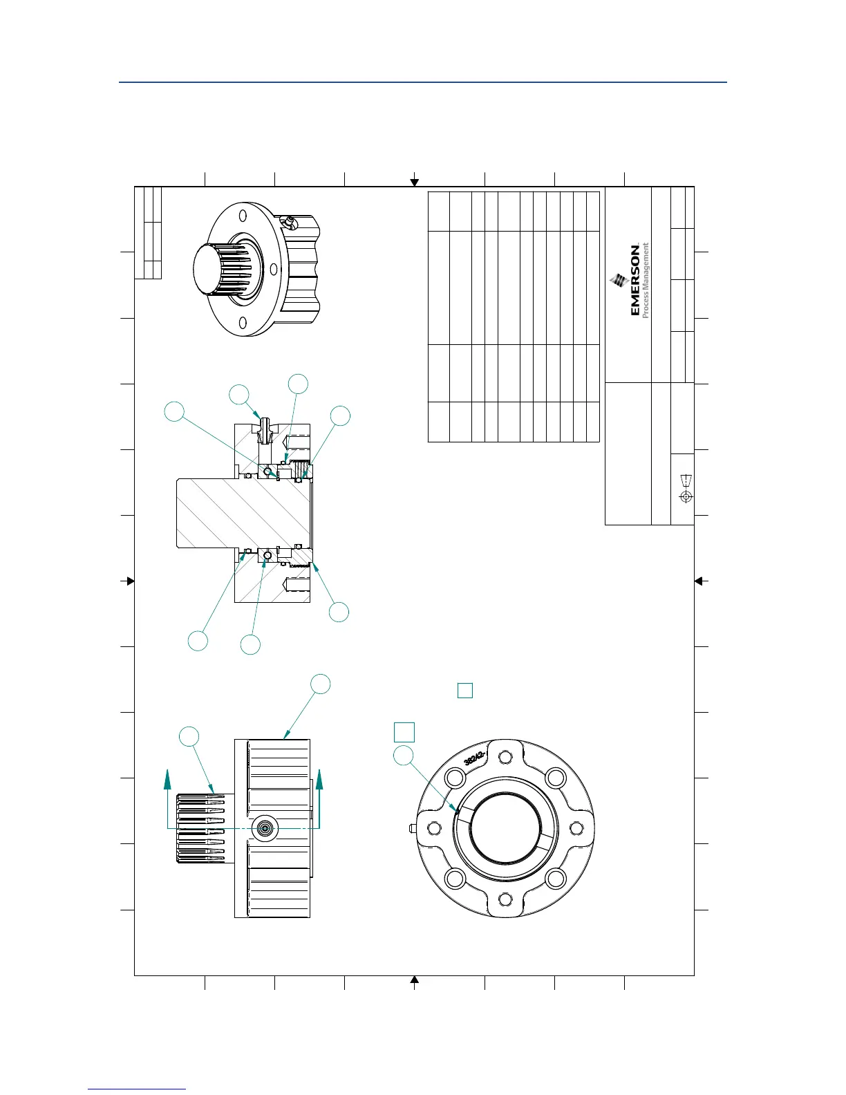
A.2 M-500 with Thrust Base Installation Drawing
REVISIONS
REV
DATE
ECN
THIRD ANGLE PROJECTION
DRAWING NO.
REV.
DRWN BY
APPROXIMATE WEIGHT
DATE
1 of 1
SHEET
A2
SCALE:
CHECKED BY
DWG. SIZE
INTERPRET DIMENSIONS AND TOLERANCE PER
ASME Y14.5
Approved BY:
87216-10
1/8/2015
Hoang, Ryan
00
Erick Nateras
Doyle Blume
Model 500 Thrust base
ISO F10 Assembly
.0 lbm
00
Released
12/31/2014
1:2
1
2
Copyright © 2014 Emerson Process Management Valve Actuation LLC
CONFIDENTIAL: This drawing, including the information it bears, is the prope
rty of Emerson Process Management Valve Actuation LLC and must
be held in strict confidence and properly safeguarded by
the recipient at all times. It may not be copied or reproduced, or provided or revealed to
any other party except with the prior written authorization o
f Emerson Process Management Valve Actuation LLC and any authorized copy or
reproduction must include this legend. The recipient may use
the same only for the purpose for which Emerson Process Management Valve
Actuation LLC has provided it to recipient, and it must be returned to Em
erson Process Management Valve Actuation LLC, along with all copies and
reproductions, upon request. By accepting this drawing, the r
ecipient agrees to the foregoing.
4
5
6
10
9
12
11
B
C
D
E
F
G
H
A
B
C
D
E
F
G
H
1
2
3
7
8
12
11
TITLE:
Item
Number
Document
Number
Title Quantity
1 38242M Model 500 Thrust Base
Housing
1
2 38244- Model 500 Stem Nut (Bronze) 1
3 38242-1M Model 500 (TB) LockNut 1
4 4000100124 TH/BRG-51110 (70x50x14mm)
- Peer
1
5 4045222617 O-Ring 568-226-70D 1
6 4060001200 Ret-Ring - 5100-2.00 1
7 4045222417 O-Ring 568-224-70D 1
8 4042205631 SHSS 1/4-20 UNC 1
9 4045214817 O-Ring 568-148-70D 1
10 4300090030 Grease fitting, 1/8-27 NPT SS 1
NOTES:
To insure locknut is secured: Drill .200 dia x .250 dp
hole, and tap 1/4-20 UNC after locknut threads have
been completely fastened to positions. Lock in place
with SHSS p/n 4042205631.
* Variable part: Refer to JOB SPEC SHEET for specific
parts for each actuator serial number.
1
1
A
A
SECTION A-A
1
2
3
4
5
6
7
8
9
10
*

 Loading...


