EasyManua.ls Logo

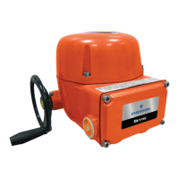
Emerson BETTIS E796 2000 M2CP User Manual

Emerson BETTIS E796 2000 M2CP
23 pages
To Next Page IconTo Next Page
Page #1 background imageLoading...
Page #1 background image
Installation and Maintenance
Part Number: E2K-402-0313, Rev. A
Release: Mar 2013
Manual E796 2000 M2CP
READ THIS MANUAL COMPLETELY
When communicating with BETTIS for replacement parts or for technical questions, we MUST have
actuator nameplate information, including Job, Serial, and Model numbers. This allows us to check
records of BETTIS equipment furnished.
When ordering parts, specify repair part by BETTIS part number and description from drawings
furnished with actuator.
BETTIS Parts Department Fax (281) 261-3834

Questions and Answers:

Emerson BETTIS E796 2000 M2CP Specifications

General IconGeneral
BrandEmerson
ModelBETTIS E796 2000 M2CP
CategoryController
LanguageEnglish

Summary

Introduction

1.1 DO

Provides essential "DO" safety and operational guidelines for actuator handling and maintenance.

1.2 DON'T

Lists critical "DON'T" actions to prevent damage, ensure safety, and maintain warranty.

1.3 Lubrication

Details factory lubricant specifications and normal operation requirements for actuator lubrication.

1.4 Maintenance

Outlines annual inspection procedures for electrical connections, damage, and lubrication checks.

1.5 Pressure Relief

Explains the function and installation of the pressure relief vent fitting for gear temperature buildup.

1.6 Short Term Storage

Provides guidelines for storing actuators safely and preventing damage from environmental factors.

1.7 Long Term Storage

Details procedures for long-term storage, emphasizing protection and warranty preservation.

M2CP Electrical Hook-Up

2.1 Electrical Hook-Up

Step-by-step guide for connecting power and control wires to the M2CP actuator, ensuring correct phasing.

Assembly to Valves

3.1 Threaded Valve Stem

Instructions for assembling the actuator to a valve with a threaded stem, including locknut installation.

3.1.1 LOCKNUT LOCKPIN INSTALLATION

Procedure for installing the locknut lockpin to secure the stem nut from loosening.

3.1.1.1 MOUNTING SCREWS

Details on mounting screw requirements and their engagement depth for secure actuator attachment.

3.1.2 THRUST SPOOL (Model 4000 & 5000)

Step-by-step instructions for assembling the thrust spool for specific actuator models.

3.1.3 SPLINE BUSHING (QUARTER TURN)

Guide for adapting the actuator to a valve with a spline shaft for quarter-turn applications.

3.2 Quarter Turn Valve

Specific assembly considerations for quarter-turn valve configurations.

3.2.1 Stop Setting Procedure (Quarter-Turn)

Detailed procedure for setting mechanical travel stops for quarter-turn valve operation.

Limit Switch Setting Instructions

BEFORE MAKING LIMIT SWITCH SETTING:

Essential pre-setting checks for voltage phasing and valve position before adjusting limit switches.

4.1 TO SET OPEN LIMIT SWITCH (LSO)

Step-by-step guide for setting the Open Limit Switch (LSO) to define the fully open position.

4.2 SET (LSC) CLOSE LIMIT SWITCH

Detailed instructions for setting the Close Limit Switch (LSC) to define the fully closed position.

4.3 TO SET INTERMEDIATE SWITCH (LSA OR LSB), if included.

Procedure for setting intermediate limit switches (LSA or LSB) if they are part of the actuator configuration.

4.4 TORQUE SEATED VALVES

Guidance for setting limit switches when dealing with torque-seated valves to ensure proper indication.

4.5 TORQUE SWITCH CALIBRATION

Procedure for calibrating the torque switches to prevent over-torquing and ensure valve protection.

4.6 To Set Open Torque Switch (TSO)

Instructions for setting the Open Torque Switch (TSO) to define the torque limit for the open direction.

4.7 Torque Switch Rotation Limit

Method for limiting the rotation of torque switches by adjusting anti-rotation pins.

Multi-turn Actuators

5.1 Calibration

Steps for calibrating the Mechanical Dial Position Indicator (MDPI) and Potentiometer after limit switch setup.

5.2 Quarter-Turn Model P, Q, R & M

Details specific gear reduction and potentiometer components for quarter-turn models.

Futronic II 83957

6.1 Calibration

Procedure for calibrating the Futronic II module, including voltage adjustments and band settings.

M2CP Wiring Diagram Symbols

Troubleshooting

Related product manuals