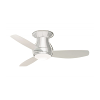
3. Ceiling Fan Assembly
M5 x 16mm FLANGE HEAD
BLADE SCREWS (3 per blade)
SLIDE FAN BLADE
INTO BLADE
CENTER SLOT
F
AN BLADE
BLADE
SLOT
FAN HOUSING
Figure 1
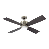
REMOVE M4 x 10mm
PAN HEAD SCREW
LOWER HOUSING
KEY HOLE
SLOT (2)
Figure 2
3.
1
P
o
si
t
i
o
n
t
h
e
f
a
n
m
o
t
o
r
a
sse
m
b
l
y
u
p
si
d
e
d
o
w
n
i
n
p
re
p
a
ra
ti
o
n
fo
r mo
u
n
ti
n
g
th
e
th
re
e
fa
n
b
l
a
d
e
s
.
S
l
i
de
b
l
ade
t
h
r
o
u
gh
b
l
a
de
s
l
o
t
i
n
f
a
n
hous
i
n
g
as
s
em
bl
y
.
Mo
u
n
t
b
l
a
d
e
to
fa
n
h
o
u
s
i
n
g
u
s
i
n
g
th
re
e
M5
x
1
6
mm
fl
a
n
g
e
h
e
a
d
b
l
a
d
e
s
c
re
w
s
(F
i
g
u
re
1
).
N
OT
E
: T
a
k
e
c
a
r
e
n
o
t to
s
c
r
a
tc
h
fa
n
h
o
u
s
in
g
a
s
s
e
m
b
ly
wh
e
n
in
s
ta
llin
g
b
la
d
e
s
.
Com
plet
e
t
he
r
em
aining
t
wo
blades
ins
t
allat
ion
per
t
he
a
b
o
v
e
i
n
s
tru
c
ti
o
n
s
.
3.2
R
e
mo
ve
o
n
e
o
f th
e
th
re
e
M4
x 1
0
mm p
a
n
h
e
a
d
scre
w
s i
n
th
e
mo
to
r h
o
u
si
n
g
a
sse
mb
l
y a
n
d
l
o
o
se
n
th
e
re
ma
i
n
i
n
g
tw
o
scre
w
s (Fi
g
u
re
2
).
At
t
ach
t
he
lower
housing
ass
em
bly
t
o
t
he
f
an
m
ot
or
by
a
l
i
g
n
i
n
g
th
e
tw
o
ke
y sl
o
t h
o
l
e
s o
f th
e
l
o
w
e
r h
o
u
si
n
g
o
n
to
th
e
mo
to
r h
o
u
si
n
g
l
o
o
se
n
e
d
scre
w
s (Fi
g
u
re
2
).
Se
cu
re
th
e
l
o
w
e
r h
o
u
si
n
g
a
sse
mb
l
y b
y ti
g
h
te
n
i
n
g
th
e
tw
o
scre
w
s.
R
e
i
n
sta
l
l
th
e
scre
w
th
a
t w
a
s p
re
vi
o
u
sl
y re
mo
ve
d
.
A spar
e M4
x 1
0
mm
p
a
n
h
e
a
d
scre
w
supplied in par
t
s bag,
if
needed.
5
emersonfans.com
Please contact 1-800-654-3545 for further assistance
U.L. Model No.: CF144 & CF152
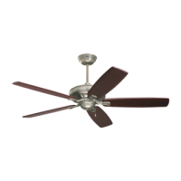
LIGHT KIT BLACK WIRE
LIGHT KIT WHITE WIRE
FAN MOTOR BLUE
WIRE
REMOVE ONE M4 x 10 mm
PAN HEAD LOWER
HOUSING SCREW
FAN MOTOR WHITE WIRE
Figure 3
3.3
R
e
mo
ve
a
n
d
re
ta
i
n
th
e
w
i
re
co
n
n
e
cto
rs
fro
m
th
e
w
h
i
te
a
n
d
b
l
u
e
w
i
re
s.
C
onnect the w
hite w
ire from the ceiling fan to the white
wire of the light k
it plate (Figure 3). Connec
t the blue wire
from
the c
eiling
fan
to the
blac
k
wire
of
the
light kit plate.
Use wire con
n
ect
ors (previously removed) to make
c
onnec
tions
.
Remove one of the three M4 x
10 mm pan head screws in
the l
ower housi
ng and l
oosen the remai
ni
ng two screws
(Figure 3).
To reduce the risk of personal injury, do not bend the
blade flange when installing the blade flanges,
balancing the blades or cleaning the fan. Do not insert
foreign objects in between rotating fan blades.
WARNING
!
To avoid possible fire or shock, the connectors should
not be removed unless immediately installing the light kit.
Power should be turned off prior to connector removal
and light kit installation.
WARNING
!