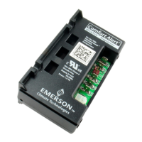
The correct Comfort Alert model must be used for the application (refer
to the Product Specifi cation section on pages 2 and 3). If the wrong model is
installed, the ALERT Flash Codes for system faults will function incorrectly: the
Comfort Alert module may indicate system faults that are not present or fail to
indicate system faults that are present.
Miswiring the Comfort Alert module will cause false LED codes. Table 1
describes LED operation when the module is miswired and what troubleshooting
action is required to correct the problem.
Miswired Module Indication Recommended Troubleshooting Action
Green LED is not on, Determine if both R and C module terminals are
module does not power up connected. Verify voltage is present at module’s R and
Green LED intermittent, Determine if R and Y terminals are wired in reverse.
module powers up only Verify module’s R and C terminals have a constant
when compressor runs source. Review
TRIP LED is on but system Verify Y terminal is connected to 24VAC at contactor
and compressor check OK coil. Verify voltage at contactor coil falls below 0.5VAC
Verify 24VAC is present across Y and C when
thermostat demand signal is present. If not, R and C are
TRIP LED and ALERT LED Verify R and C terminals are supplied with 19-28VAC.
ALERT Flash Code 3 Verify Y terminal is connected to 24VAC at contactor coil.
(Compressor Short Cycling) Verify voltage at contactor coil falls below 0.5VAC when
displayed incorrectly off.
ALERT Flash Code 5, 6 or 7 Check that compressor run and start wires are through
(Open Circuit, Open Start Circuit module’s current sensing holes. Verify Y terminal is
or Open Run Circuit) displayed connected to 24VAC at contactor coil. Verify voltage at
incorrectly contactor coil falls below 0.5VAC when off.
ALERT Flash Code 6 (Open Check that compressor run and start wires are routed
Start Circuit) displayed for Code 7 through the correct module sensing holes.
(Open Run Circuit) or vice versa
ALERT Flash Code 8 Determine if module’s Y terminal is connected. Verify Y
(Welded Contactor) terminal is connected to 24VAC at contactor coil. Verify
displayed incorrectly 24VAC is present across Y and C when thermostat
signal is present. If not, R and C are reverse
wired. Verify voltage at contactor coil falls below 0.5VAC
 Loading...
