105
Installation
(ECI-44) which provides a convenient screw terminal connection strip. Connect one end of
the CMDX command cable to your drive and the other end to the ECI-44.
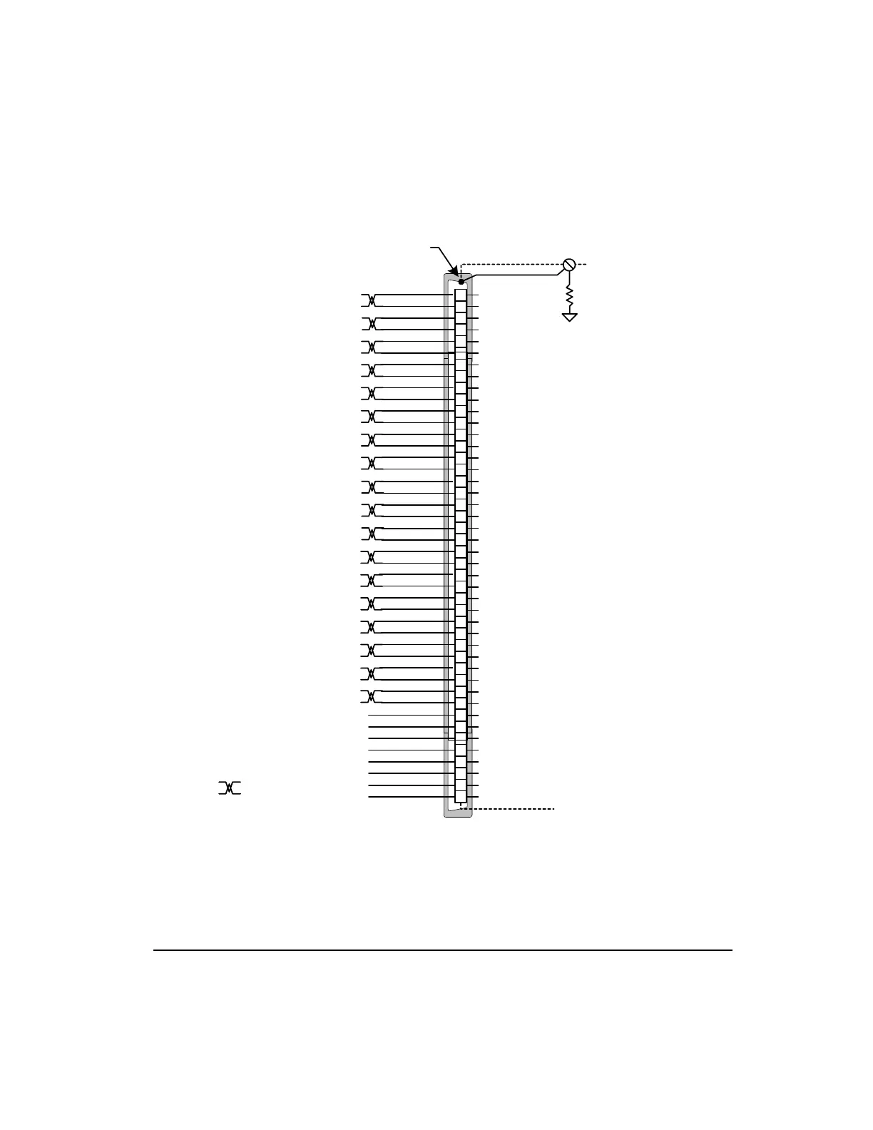
Figure 77: Command Connector (J5) Pinout and CMDO-XXX Wire Colors
1
2
3
4
5
6
7
8
9
10
11
12
13
14
15
16
17
18
19
20
21
22
23
24
25
26
27
28
29
30
31
32
33
34
35
36
37
38
39
40
41
42
43
44
Input #1
Input #2
Input #3
Input #4
RS 485+
Encoder Output Channel A
Encoder Output Channel A/
Encoder Supply +5 Volts - Output. 200 mA
Encoder Common
- Analog Command In
+ Analog Command In
Drive Enable Input
Output #3
Output #2
Output #1
RS 485-
Encoder Output Channel B
Encoder Output Channel B/
Diagnostic Output Common
I/O Common -
I/O Common -
I/O Supply +
I/O Supply +
Encoder Output Channel Z
Encoder Output Channel Z/
Diagnostics Output Channel 1
Diagnostics Output Channel 2
Command Connector
Do Not Connect
Do Not Connect
Do Not Connect
Do Not Connect
Do Not Connect
Do Not Connect
Do Not Connect
Do Not Connect
Shield
PE
10 Ohm
Connector Shell
Connected to
+15 Out (Test Only)
= Twisted Pair
Pulse Input B
Pulse Input B/
Pulse Input A/
Pulse Input A
Pulse Input Z/
Pulse Input Z
Pulse In B Single-ended
Pulse In A Single-ended
(YEL/BRN)
(BRN/YEL)
(BRN/PRP)
(PRP/BRN)
(GRY/PRP)
(PRP/GRY)
(BLU/WHT)
(WHT/BLU)
(RED/WHT)
(WHT/RED)
(GRN/WHT)
(WHT/GRN)
(BLK/GRN)
(PRP/GRN)
(YEL/BLU)
(BLU/YEL)
(GRN/PRP)
(GRN/BLK)
(PRP/ORG)
(BLK/RED)
(RED/BLK)
(ORG/PRP)
(BLK/BRN)
(BRN/BLK)
(BLK/BLU)
(PRP/BLU)
(BLU/RED)
(RED/BLU)
(BLU/PRP)
(ORG/WHT)
(WHT/ORG)
(BLU/BLK)
(BRN/RED)
(RED/BRN)
(GRY/YEL)
(YEL/GRY)
Artisan Technology Group - Quality Instrumentation ... Guaranteed | (888) 88-SOURCE | www.artisantg.com
 Loading...