2-36 / Installation & Operation CI-ControlWave EFM
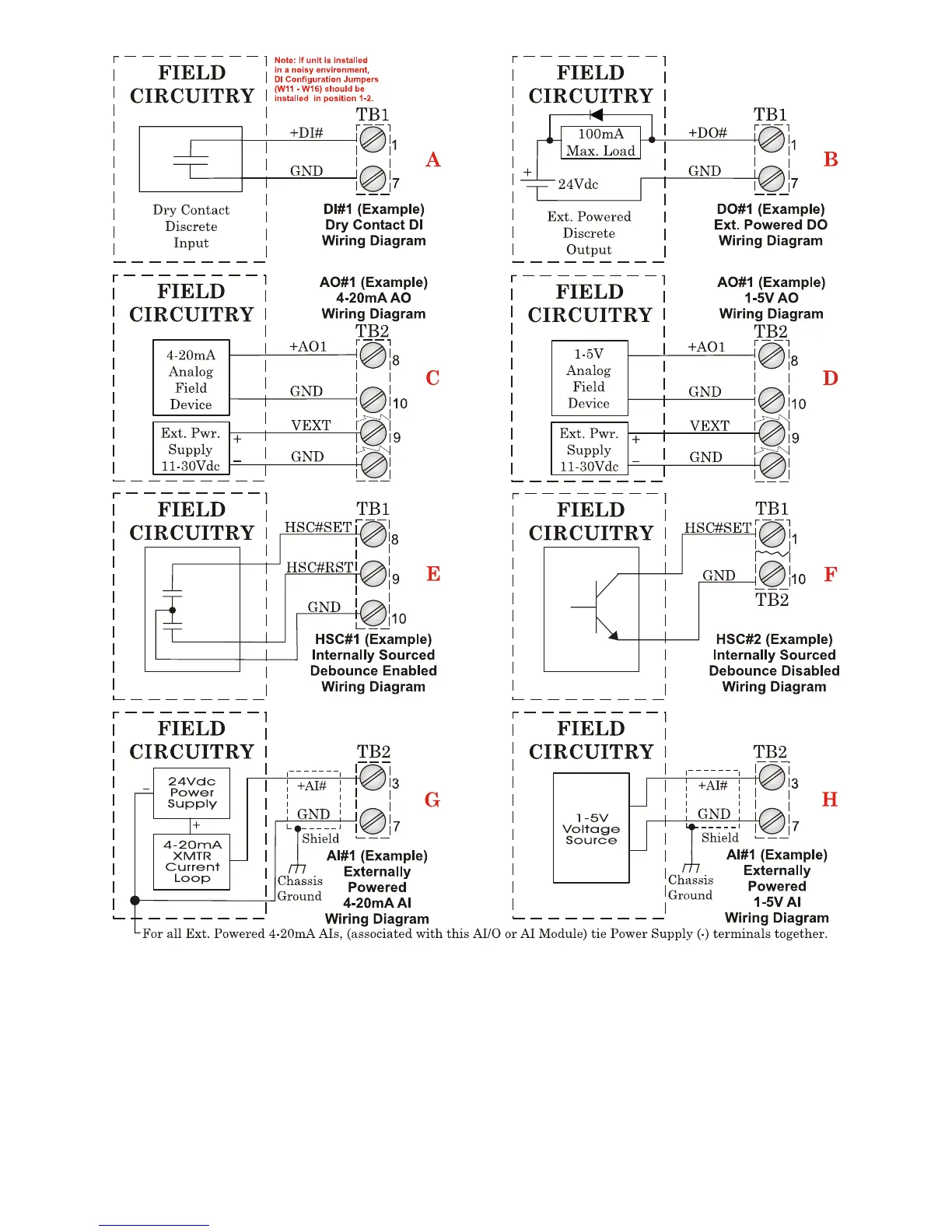
Figure 2-22 - Mixed I/O Module Wiring Diagram
Mixed I/O Modules optionally support one externally powered (VEXT = 11 to 30Vdc) analog
output. AO Circuitry consists of a 12-bit resolution Digital to Analog Converter (DAC), a V
to I circuit, and a V to V circuit. The 12-bit DAC drives the V to I circuitry. A scaling circuit
within the V to I circuit drives the V to V circuitry. V to I and V to V circuitry are powered
by an external power source.