CI-ControlWave EFM Installation & Operation / 2-37
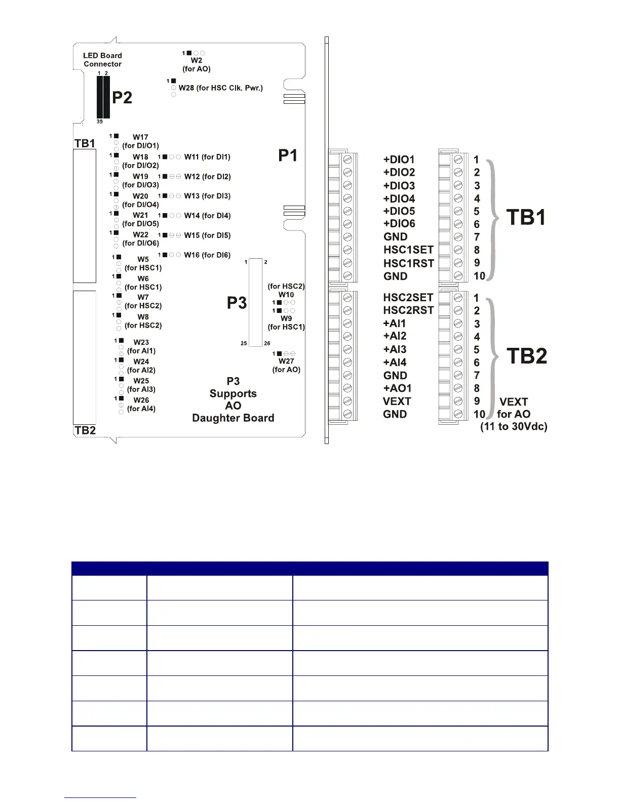
Figure 2-23 - Non Isolated Mixed I/O Module Configuration Diagram
2.3.4.7.1 Mixed I/O Module Configurations
Mixed I/O Module Configuration Jumpers W1 through W28 must be set per Table 2-11.
Table 2-11 - Non Isolated Mixed I/O Module Jumper Assignments
Jumper Purpose Notes
W1*
Configures optional AO for
Voltage or Current Output
Pins 1-2 installed = AO set for Current Output
Pins 2-3 installed = AO set for Voltage Output
W2
Configures optional AO for
Voltage or Current Output
Pins 1-2 installed = AO set for Voltage Output
Pins 2-3 installed = AO set for Current Output
W5 & W6 HSC1 Current Control
Pins 1-2 installed = for additional 2mA load
Pins 2-3 installed = 200uA Source no 2mA load
W7 & W8 HSC2 Current Control
Pins 1-2 installed = for additional 2mA load
Pins 2-3 installed = 200uA Source no 2mA load
W9 & W10
Configures HSC1 and HSC2
Debounce (respectively)
Pins 1-2 installed = Enables HSC Debounce
Pins 2-3 installed = Disabled HSC Debounce
W11 - W16
Configures DI1 through DI6
Current (respectively)
Pins 1-2 installed = 2mA Source Current
Pins 2-3 installed = 60uA Source Current
W17 - W22
DI/O1 through DI/O6 Point
Selection (respectively)
Pins 1-2 installed = Digital Input Operation
Pins 2-3 installed = Digital Output Operation