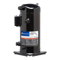
22 AGL_Stream_ST_A2L_A1_4M_6M_EN_Rev00
Figure 25: Wiring diagram – Part-winding and Star/Delta motors (AW… & EW…)
Legend
B1 Discharge gas sensor DGT Discharge gas temperature monitoring
B2 Oil level watch (TraxOil) OW Digital oil level watch
B3 Oil differential pressure switch (OPS) OPS Oil differential pressure protection
B11 High-pressure switch AR Alarm relay
B12 Low-pressure switch DS Run/control signal
CTR2 DP Gateway
E1 Heater CH Control oil heater
F1, F2, F3 Compressor fuses PTC Motor thermic protection
F4, F5 Fan fuses PM Phase monitoring
F6 Module and heater fuse PS Power supply
F7 Control circuit fuse
H1 Diagnosis LED K11 Time relay for part winding (if used)
M2 Fan motor
Q11 Compressor contactor Q15 Fan contactor
Q12 Compressor contactor Y (if Y/Δ start) Q13 Compressor contactor Δ (if Y/Δ start)
Q14 Compressor contactor 2
nd
part winding (if used)
SB1 Reset button
Y21 Solenoid valve capacity control 1 Y22 Solenoid valve capacity control 2
T1 Current sensor CM Current monitoring

 Loading...