13
© 2011 Emerson Climate Technologies
Printed in the U.S.A.
AE5-1377 R2
Application Engineering
BULLETIN
*
Lockout feature can be reset by disconnecting the unit power source
and then reconnection of the unit power source.
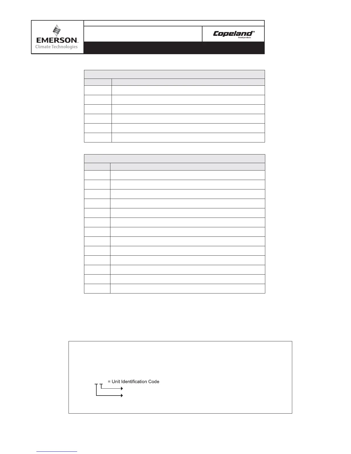
88
(1second) ->
02
(3 seconds) ->
-F
(3 seconds) ->
00
02
= Software Version No.
-F
“F”- With OD Fan Speed Control; “-” = W/O OD Fan Speed Control
“L”- LT; “-” = MT
00
= Power On
Delay Firmware Unit Revision Stator
LED1 - Unit Status
Display Status
0
Idle (Stop When Reach To Set-point)
1
Run
2
About To Start
1
3
Defrost
4
Unit Trip
5
Unit Lockout
LED2 - Error/Warning Code
Display Error/Warning
0
No error/warnings
1
Compressor Phase Error (Wrong Phase Sequence/Loss Of Phase)
2
Compressor Inside Internal Motor Protector Trip
3
Compressor Over Current
4
Discharge Gas Overheat (High Discharge Temperature)
5
Compressor High Pressure Cut Out
6
Not Used
7
DLT Thermistors Failure
8
Ambient Temperature Sensor Failure
9
Mid-coil Temperature Sensor Failure
a
PHE Vapor In Temperature Sensor Failure or over range
2
C
PHE Vapor Out Temperature Sensor Failure or over range
2
e
System Liquid Flood Back Warning
Note:
1
This signal is for Fresh Start, Normal Start Program and any start request delay.
2
PHE Vapor In/Out Temperature Sensor is not applicable in XJAM condensing unit (MT units).
All error/warning messages are priority-ranked from highest to lowest.
If unit is initially powered on, the diagnosis module will show signal similar to the below example:
Table 6 – Diagnostics Module Display
Table 6a – Diagnostics Module Display
Diagnostics Module Start Up Information
 Loading...