6
© 2011 Emerson Climate Technologies
Printed in the U.S.A.
AE5-1377 R2
Application Engineering
BULLETIN
X J A M - 0 2 0 Z - T F C - 0 0 2
Family X-Line
J = R404A
A = Air-Cooled
0 = UL Listed
Product
CFV = 208/230V-1ph-60Hz
TFC = 208/230V-3ph-60Hz
1.5 to 6.0 = Nominal Hp
M = Medium Temp
L = Low temp
Z = Scroll
Model Variation
0 Base Unit
1 Communication/
Defrost Module
2 Low Ambient /
On Board Defrost Relays
XJAM XJAL XJAM XJAL XJAM XJAL
-002 -002 -012 -012 -022 -022
Fan Motor Variable Variable Variable Variable Variable Variable
Head Pressure Control VS VS VS VS VS VS
Hood X X XXXX
Service Valves Brass Brass Brass Brass Brass Brass
Moisture Indicator X X X X X X
CCH X X X X X X
Defrost mer X X X
One Way Communicaon XXXX
3 Minute An-Short Cycling X X XXXX
20 Second An-Short Cycling Opon X X X X
Defrost mer w/ Relays X X
Heated Insulated Receiver X X
Low Pressure Bypass Time Delay X X
Incorrect Phase Rotaon
X X XXXX
Liquid Flood-Back Predicon
X X XXXX
"Fresh" Start Logic
X X XXXX
Compressor Overheang
X X XXXX
Compressor Short Cycle
X X XXXX
Fault Code History
X X XXXX
X X XXXX
BOM
FeaturesDiagnoscs
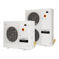
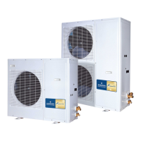
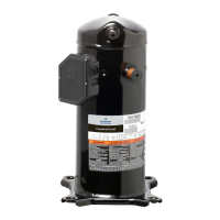
Figure 1 – Nomenclature and Features
code as shown in Table 6a. See Figure 5 for a detailed
view of the diagnostics board assembly.
The Main Board Connector terminal will accept the cable
connecting the display board to the main control board.
The Reset Button will reset the diagnostic display board
only. The Message Recall Button will display the last
error signal received by the display board. See Figure 5.
 Loading...