Application Engineering
B U L L E T I N
AE8-1386 R1
Systems with Compressor Pumpdown Cycle Mounting and Installation
In systems that require a compressor pumpdown,
special attention should be paid to the control logic
for the digital unloader coil. Inherent to the digital
control, the compressor will effectively ramp down and
track the suction pressure by loading and unloading
to decreasing modulation rates. In order to avoid an
extended compressor pumpdown cycle, the digital
solenoid should be wired/controlled such that when a
pump down cycle is initiated the coil is de-energized.
This will force the compressor to run fully loaded (100%
capacity). Refer to AE-1182 and AE-1221 for more
details on pumpdown cycles.
Note: The Digital unloader solenoid is always energized
for 2 seconds upon start-up and at shut down of the
compressor.
PANEL
BRACKET
If this controller is used outside, it should be enclosed in a
box with IP65 rating. Controllers should be mounted on
panel, in a 29x71 mm (1.14x2.80 inch) hole, and
fixed using the special brackets supplied. The controller
should not be mounted on the compressor nor in the
compressor terminal box.
The ambient operating temperature range is between
14-140 degrees F. (Can operate in ambients as low as
-40°F when applied with an enclosure.)
Ensure ventilation around the controller.
Note! For systems applied in low ambient conditions,
special attention should be paid to the digital
compressor's minimum allowable pressure differential
(Absolute Discharge Pressure - Absolute Suction
Pressure). Copeland Scroll compressors must maintain
at least a 75 PSID while the Copeland Discus must have
a 45 PSID to operate correctly.
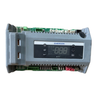
(PUSH TO RELEASE)
•3.1”
•Front
•2.6”
•Back
•Side
Figure 5 - XC643 Dimensions and Mounting
© 2013 Emerson Climate Technologies, Inc.
8
Printed in the U.S.A.

 Loading...