2
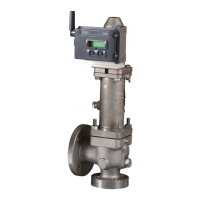
CROSBY J SERIES PRESSURE RELIEF VALVE WITH FISHER™ 4320 WIRELESS POSITION MONITOR
INSTALLATION, OPERATION AND MAINTENANCE MANUAL
WARNING
Sudden release of pressure may result if the valve
assembly is installed where service conditions
could exceed the limits on the appropriate
nameplates. Never use this equipment for any
purpose other than its intended use.
This manual is provided as a general guide for the
assembly or retrofit on the pressure relief valves
described herein. It is not possible to describe all
configurations or variations with such equipment.
The user is advised to contact Emerson or its
authorized assemblers and representatives for
assistance in situations that are not adequately
covered or described in this manual.
Failure to do so may result in injury to personnel
or cause damage to the equipment.
WARNING
Avoid personal injury from sudden release
of process pressure. Before performing any
maintenance operations:
• Do not remove any component from the valve
while the valve is still pressurized.
• Always wear protective gloves, clothing, and
eyewear when performing any maintenance
operations to avoid personal injury.
• Adhere to all safety standards and best
practices for operating the equipment.
• Use bypass valves or completely shut off the
process to isolate the valve from process
pressure. Relieve process pressure on both
sides of the valve. Drain the process media from
both sides of the valve.
• Use lock-out procedures to be sure that the
above measures stay in effect while you work on
the equipment.
• The valve may contain process media that are
pressurized, even when the valve has been
removed from the process.
• Check with your process or safety engineer for
any additional measures that must be taken to
protect against process media.
Failure to do so may result in injury to personnel
or cause damage to the equipment.
The escape of process media indicates that the
valve has NOT been properly vent, or process
pressure is trapped in the valve body. Check
with your process or safety engineer for any
additional measures that must be taken to
protect against process media. Never attempt
to remove the pressure relief valve from a
system that is pressurized. Never adjust
or perform maintenance on the pressure
relief valve while in service unless the valve
is isolated from the system pressure. If not
properly isolated from the system pressure,
the pressure relief valve may inadvertently
open resulting in serious injury. Remove the
pressure relief valve prior to performing any
pressure testing of the system.
2.1 Magnetic Sensor Size Selection
To achieve an accurate valve position, the
correct magnet size must be selected. Refer to
Table 1 for selection.
CAUTION
The magnet material has been specifically chosen
to provide a long-term stable magnetic field.
However, as with any magnet, care must be taken
when handling the magnet assembly. Another
high-powered magnet placed in close proximity
(less than 25 mm) can cause permanent damage.
Potential sources of damaging equipment include,
but are not limited to: transformers, dc motors,
stacking magnet assemblies.
Failure to do so may result in equipment mal
function.
Tip: As a general rule, do not use less than 50% of
the magnet assembly for full travel measurement.
Performance will decrease as the assembly
is increasingly subranged. The linear magnet
assemblies have a valid travel range indicated by
arrows molded into the piece. This means that the
hall sensor (on the back of the 4320 housing) has to
remain within this range throughout the entire valve
travel. The linear magnet assemblies are symmetrical.
Either end may be up.
2 CALIBRATION PROCEDURE
CAUTION
When the pressure relief valve is under pressure
never place any part of your body near to the
outlet/exhaust of the valve. Never use this
equipment for any purpose other than its intended
use.
Failure to do so may result in injury to personnel
or cause damage to the equipment.
CAUTION
When the pressure relief valve is under pressure
never place any part of your body near to the
outlet/exhaust of the valve. Failure to do so may
result in injury to personnel or cause damage to
the equipment.
CAUTION
This product is intended for a specific temperature
range and other application specifications.
Failure to adhere to these specifications could
result in the malfunction of the product, property
damage, or personal injury.
WARNING
If the process media starts to escape from the
valve or pilot, stop immediately!
Failure to do so may result in injury to personnel
or cause damage to the equipment.
The safety of lives and property often depends
on the proper operation of the pressure relief
valve. The valve must be maintained according
to appropriate instructions and must be
periodically tested and reconditioned to ensure
correct function.
WARNING
Use only genuine Emerson replacement parts.
Components that are not supplied by Emerson
should not, under any circumstances, be used.
Use of components not supplied by Emerson
may void your warranty, might adversely affect
the performance of the instrument and could
cause personal injury or property damage.
Failure to do so may result in injury to
personnel or cause damage to the equipment.
NOTICE
Contact your Emerson sales office for
replacement parts.
Before installation, the Installation and
Operational Safety Instructions should be fully
read and understood. These Instructions may
be requested from the factory or are available
at Emerson.com.
 Loading...


