3
CROSBY J SERIES PRESSURE RELIEF VALVE WITH FISHER™ 4320 WIRELESS POSITION MONITOR
INSTALLATION, OPERATION AND MAINTENANCE MANUAL
2.2 Calibration
Mounting the Fisher 4320 Wireless
Position Monitor
1. Install a battery into the Fisher 4320
Wireless Position Monitor.
WARNING
Due to the combustible nature of the lithium
content, the power module has special
installation, operation, storage, and/or shipping
requirements. Observe all warnings included with
the power module before installing, operating,
storing, or shipping the 4320 Position monitor.
Failure to do so may result in personal injury or
property damage from fire or explosion.
CAUTION
When installing components, proper means of
electrostatic discharge protection is required.
Failure to use a grounding strap, or other means
of electrostatic discharge protection can result in
damage to the electronics.
CAUTION
To avoid static discharge do not rub or clean the
antenna with solvents.
Failure to do so may result in personal injury or
property damage from fire or explosion.
2. Mount the 4320 to the bracket and lightly
tighten screws enough to hold in place. The
screws will be tightened once calibration
step is complete.
3. Mount the calibration plate and bracket on
the pressure relief valve bonnet as shown
on Figure 2-2.
WARNING
Due to the combustible nature of the lithium
content, the power module has special
installation, operation, storage, and/or shipping
requirements. Observe all warnings included with
the power module before installing, operating,
storing, or shipping the 4320 Position monitor.
Failure to do so may result in personal injury or
property damage from fire or explosion.
4. Slide the Polytetrafluoroethylene (PTFE)
bushing sleeve on the magnet bracket.
The PTFE open slot should face in down
direction.
5. Secure the Magnet in place under the bend
in the Magnet Bracket with 2 screws and
lock washers provided with Magnet. Torque
force listed in Table 2, Location 1.
6. Position the magnet bracket assembly to
the valve stem at the dimension “A” shown
in Table 1. Lock in place.
7. Verify dimension “A” by caliper or depth
micrometer to ensure it is in the tolerance
as shown in the Table 1.
8. Loosen the Screws on 4320 Bracket and line
up the mark on the back of 4320 with the top
mark on the magnet. Lock 4320 in place on
Bracket with quantity of 4, M6 x 10mm HEX
CAP Screws and Lock Washers with Torque
force listed in Table 2, Location 2. Center
the magnet assembly inside the 4320 slot by
slightly adjusting the magnet bracket, if it is
needed. This represents the “0% position”,
valve closed.
CAUTION
Do not install a magnet assembly that is shorter
than the physical travel of the valve. Loss of
control will result from the magnet assembly
moving outside the range of the index mark in the
feedback slot of the 4320 housing.
Failure to do so may result in personal injury or
property damage.
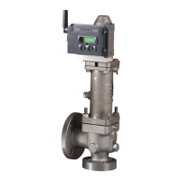
FIGURE 2-1
4320 and Bracket Assembly
FIGURE 2-2
Magnet Alignment
FIGURE 2-3
Measurement for Dim A
FIGURE 2-4
Measurement for Dim A
 Loading...


