4
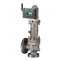
CROSBY J SERIES PRESSURE RELIEF VALVE WITH FISHER™ 4320 WIRELESS POSITION MONITOR
INSTALLATION, OPERATION AND MAINTENANCE MANUAL
Mark valve closed position (0%)
1. On the 4320, press the right button until
CALIBRATE appears.
Mark valve full lift (100%)
1. After the 0% position has been MARKED
press NEXT to select the second calibration
point, 100% valve lift.
FIGURE 2-5
Wake up the 4320
FIGURE 2-8
First Point Set
FIGURE 2-9
First Point Mark
FIGURE 2-10
First Point Mark
CAUTION
When accessing the pushbuttons or terminals
proper means of electrostatic discharge
protection is required.
Failure to provide appropriate protection can
cause the device to malfunction.
2. Push SELECT, this will allow you to select
the first calibration point to be used, 0%.
FIGURE 2-6
Calibrate Window
FIGURE 2-7
First Point Calibration
3. Push the right button to select 0%.
4. Once set in position, use the left button to
toggle the recording position to MARKED.
MARKED indicates that the location has
been recorded; UNMARKED indicates that
position has not been recorded.
2. Loosen the two Spindle Nuts, move the
magnet up to the full lift dimension and get
the dimension “B” shown in Table 1. Lock in
place.
3. Measure dimension B by caliper or depth
micrometer to ensure it is in the tolerance
as shown in the Table 1.
NOTICE
The valve must move from open to closed, or vice
versa, in order for the wireless position monitor to
be calibrated. Attempting to calibrate the device
without moving the valve will result in the action
being discarded. The operation of the device will
be unchanged.
 Loading...


