EasyManua.ls Logo

Emerson dixell WING XW260L - User Manual

Emerson dixell WING XW260L
4 pages
Print Icon
To Next Page IconTo Next Page
Loading...
1592009027 XW260L GB r1.0 03.08.2015 XW260L 1/4
WING
XW260L
1. GENERAL WARNING
1.1 PLEASE READ BEFORE USING THIS MANUAL
This manual is part of the product and should be kept near the instrument for easy and quick reference.
The instrument shall not be used for purposes different from those described hereunder. It cannot be used
as a safety device.
Check the application limits before proceeding.
Dixell Srl reserves the right to change the composition of its products, even without notice, ensuring the
same and unchanged functionality.
1.2
SAFETY PRECAUTIONS
Check the supply voltage is correct before connecting the instrument.
Do not expose to water or moisture: use the controller only within the operating limits avoiding sudden
temperature changes with high atmospheric humidity to prevent formation of condensation
Warning: disconnect all electrical connections before any kind of maintenance.
Fit the probe where it is not accessible by the End User. The instrument must not be opened.
In case of failure or faulty operation send the instrument back to the distributor or to Dixell S.r.l..” (see
address) with a detailed description of the fault.
Consider the maximum current which can be applied to each relay (see Technical Data).
Ensure that the wires for probes, loads and the power supply are separated and far enough from each
other, without crossing or intertwining.
In case of applications in industrial environments, the use of mains filters (our mod. FT1) in parallel with
inductive loads could be useful.
2. GENERAL DESCRIPTION
Model XW260L, 38x185 mm format, is microprocessor based controller suitable for applications on medium or
low temperature refrigerating units. It is provided with four relay outputs to control compressor, defrost - which
can be either electrical or hot gas - the evaporator fans and the lights.
It is also provided with three NTC probe inputs, one for temperature control, one to control the defrost end
temperature of the evaporator and the third, optional, for the display. There are two digital inputs (free contact)
for the door switch and configurable by parameter.
The standard TTL output allows the user to connect, by means of a TTL/RS485 external module, a ModBUS-
RTU compatible monitoring system and to programme the parameter list with the “Hot Key”.
An optional output for remote display “XW-REP” is available.
3. CONTROLLING LOADS
3.1 THE COMPRESSOR
The regulation is performed according to the temperature measured by the thermostat probe with a positive
differential from the set point: if the temperature increases and reaches set point plus differential the compressor
is started and then turned off when the temperature reaches the set point value again.
In case of fault in the thermostat probe the start and stop of the compressor are timed through parameters
COn” and “COF”.
3.2 FAST FREEZING
When defrost is not in progress, it can be activated the keypad by holding the o key pressed for about 3
seconds. The compressor operates in continuous mode for the time set through the “CCt” parameter. The cycle
can be terminated before the end of the set time using the same activation key, o for about 3 seconds.
3.3 DEFROST
Three defrost modes are available through the tdF parameter: defrost with electrical heater, hot gas or
thermostatic defrost. The defrost interval is control by means of parameter EdF”: (EdF=in) the defrost is made
every IdF time, (EdF=Sd) the interval “IdF” is calculate through Smart Defrost algorithm (only when the
compressor is ON and the evaporator temperature is bigger than “SdF” parameter).
At the end of defrost the drip time is controlled through the “Fdt” parameter.
3.4 CONTROL OF EVAPORATOR FANS
The fan control mode is selected by means of the “FnC” parameter:
FnC=C-n fans will switch ON and OFF with the compressor and not run during defrost:;
FnC=C-y fans will run continuously, but not during defrost
After defrost, there is a timed fan delay allowing for drip time, set by means of the “Fnd” parameter.
FnC=O-n fans will switch ON and OFF with the compressor and run during defrost;
FnC=O-y fans will run continuously also during defrost
An additional parameter “FSt” provides the setting of temperature, detected by the evaporator probe, above
which the fans are always OFF. This can be used to make sure circulation of air only if his temperature is lower
than set in “FSt”.
4. KEYBOARD
FF
FC
To display and modify target set point; in programming mode it selects a parameter or confirm an
operation.
By holding it pressed for 3s when max or min temperature is displayed it will be erased.
To see the max. stored temperature; in programming mode it browses the parameter codes or
increases the displayed value. By holding it pressed for 3s the fast freezing cycle is started.
To see the min stored temperature; in programming mode it browses the parameter codes or
decreases the displayed value.
By holding it pressed for 3s the defrost is started.
Switch ON and OFF the cold room light.
Switch ON and OFF the instrument.
KEY COMBINATIONS
+
To lock and unlock the keyboard.
+
To enter the programming mode.
+
To exit the programming mode.
4.1 USE OF LEDS
Each LED function is described in the following table.
LED
MODE
Function
ON
The compressor is running
FLASHING
- Programming Phase (flashing with LED )
- Anti-short cycle delay enabled
ON
The fan is running
FLASHING
Programming Phase (flashing with LED )
ON
The defrost is enabled
FLASHING
Drip time in progress
ON
The Fast Freezing cycle is enabled
ON
- ALARM signal
- In “Pr2” indicates that the parameter is also present in “Pr1”
Function of the LEDs placed on the left top side of buttons:
BUTTON
MODE
FUNCTION
SET
FLASHING
The Set point is displayed and it can be modified
SET
FAST FLASHING
The Energy Saving is enabled
DEFROST
ON
The Manual Defrost is activated
LIGHT
ON
The Light is ON
ON/OFF
ON
The instrument is OFF
4.2 HOW TO SEE THE MIN TEMPERATURE
1. Press and release the n key.
2. The “Lo” message will be displayed followed by the minimum temperature recorded.
3. By pressing the n key or waiting for 5s the normal display will be restored.
4.3 HOW TO SEE THE MAX TEMPERATURE
1. Press and release the o key.
2. The “Hi” message will be displayed followed by the maximum temperature recorded.
3. By pressing the o key or waiting for 5s the normal display will be restored.
4.4 HOW TO RESET THE MAX AND MIN TEMPERATURE RECORDED
To reset the stored temperature, when max or min temperature is displayed :
1. Press SET key until “rST” label starts blinking.
N.B. After the installation RESET the temperature stored .
4.5 HOW TO SEE AND MODIFY THE SET POINT
1. Push and immediately release the SET key: the display will show the Set point value;
2. The SET LED start blinking;
3. To change the Set value push the o or n arrows within 10s.
4. To memorise the new set point value push the SET key again or wait 10s.
4.6 TO START A MANUAL DEFROST
1. Push the DEF key for more than 2 seconds and a manual defrost will start.
4.7 TO ENTER IN PARAMETERS LIST “PR1”
To enter the parameter list “Pr1” (user accessible parameters) operate as follows:
1. Enter the Programming mode by pressing the Set and DOWN key for few
seconds ( and
start blinking).
Question and Answer IconNeed help?

Do you have a question about the Emerson dixell WING XW260L and is the answer not in the manual?

Summary

General Warnings and Precautions

Safety Precautions

Essential safety measures to follow before operating the instrument.

Manual Reference

Instructions to keep the manual accessible for quick reference.

Device Overview and Operation

XW260 L Description and Load Control

Overview of the controller and its functions: compressor, fast freezing, defrost, and fans.

User Interface and Parameter Access

Keyboard, LEDs, temperature monitoring, set point adjustment, and parameter access.

Parameter Access and Basic Operation

Parameter List Access, Keyboard Control, and Power

Steps to enter parameter lists and manage keyboard lock/unlock and instrument power.

Viewing Probe Data

How to access and display readings from connected probes.

Core Parameter Configurations

Regulation, Display, and Defrost Settings

Configuration of temperature regulation, display options, and defrost modes.

Fan, Alarm, Input, and Miscellaneous Settings

Settings for fan control, alarms, inputs, and other device parameters.

Digital Input Configuration

Input Functions and Polarity

Defines door switch and configurable input functions, including polarity.

Installation, Connections, and Hot Key Use

Mounting, Environment, and Wiring

Panel mounting, environmental conditions, wiring, and load limits.

Probe and Serial Line Connections

Guidelines for probe installation and connecting to serial lines.

Hot Key Programming Operations

Procedures for transferring parameters to and from the Hot Key device.

Alarm Signals and Management

Alarm Messages, Causes, and Recovery

Details on alarm messages, their causes, buzzer silencing, and recovery.

Technical Data and Connections Diagram

Physical and Electrical Specifications

Housing, mounting, power, inputs, outputs, and communication details.

Operating Ranges and Accuracy

Information on measurement ranges, operating temperature, and accuracy.

XW260 L Wiring Diagram

Visual representation of electrical connections for the XW260L unit.

Overview

The Dixell XW260L is a microprocessor-based controller designed for medium and low-temperature refrigerating units. It offers comprehensive control over various aspects of a refrigeration system, including the compressor, defrost cycles, evaporator fans, and lighting.

Function Description

The XW260L features four relay outputs to manage the compressor, defrost (which can be either electrical or hot gas), evaporator fans, and the cold room lights. It is equipped with three NTC probe inputs: one for temperature control, another for monitoring the defrost end temperature of the evaporator, and a third optional probe for display purposes. Additionally, the device includes two configurable digital inputs (free contact) for functions like a door switch or other programmable actions.

The regulation of the compressor is based on the temperature measured by the thermostat probe. The compressor starts when the temperature rises to the set point plus a positive differential and stops when it reaches the set point value again. In case of a thermostat probe fault, the compressor's start and stop times are managed by the "COn" and "COF" parameters.

The device supports a "Fast Freezing" function, which can be activated manually when defrost is not in progress. This mode forces the compressor to operate continuously for a time set by the "CCt" parameter.

Three defrost modes are available via the "tdF" parameter: electrical heater, hot gas, or thermostatic defrost. The defrost interval is controlled by the "EdF" parameter. If "EdF=in," defrost occurs at fixed "IdF" intervals. If "EdF=Sd," the "IdF" interval is calculated using a Smart Defrost algorithm, which activates only when the compressor is ON and the evaporator temperature exceeds the "SdF" parameter. A drip time, controlled by the "Fdt" parameter, is managed at the end of the defrost cycle.

Evaporator fan control is configured by the "FnC" parameter. Options include fans switching ON/OFF with the compressor and not running during defrost (FnC=C-n), running continuously but not during defrost (FnC=C-y), switching ON/OFF with the compressor and running during defrost (FnC=O-n), or running continuously during defrost (FnC=O-y). A timed fan delay, set by "Fnd," allows for drip time after defrost. An additional parameter, "FSt," ensures that fans only operate if the evaporator temperature is below a specified value, preventing air circulation when the temperature is too high.

The XW260L also includes alarm management for various conditions, such as probe failures (thermostat, evaporator, auxiliary), maximum/minimum temperature alarms, data/memory failure, defrost timeout, door switch alarms, and external alarms. A buzzer signals these alarms, which can be silenced by pressing any key.

Usage Features

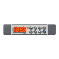
The user interface includes a set of buttons and LEDs for easy operation and monitoring.

  • The SET button is used to display and modify the target set point, select parameters, or confirm operations in programming mode. Holding it for 3 seconds erases max/min temperature records.
  • The UP arrow button allows viewing the maximum stored temperature, browsing parameter codes, or increasing displayed values. Holding it for 3 seconds starts the fast freezing cycle.
  • The DOWN arrow button allows viewing the minimum stored temperature, browsing parameter codes, or decreasing displayed values. Holding it for 3 seconds starts defrost.
  • The LIGHT button switches the cold room light ON/OFF.
  • The ON/OFF button switches the instrument ON/OFF.

Key combinations provide additional functionalities:

  • UP + DOWN locks and unlocks the keyboard.
  • SET + DOWN enters the programming mode.
  • SET + UP exits the programming mode.

LED indicators provide visual feedback on the device's status:

  • A steady compressor LED indicates the compressor is running. A flashing compressor LED indicates a programming phase or anti-short cycle delay.
  • A steady fan LED indicates the fan is running. A flashing fan LED indicates a programming phase.
  • A steady defrost LED indicates defrost is enabled.
  • A flashing defrost LED indicates drip time in progress.
  • A steady alarm LED indicates an alarm signal.
  • A steady fast freezing LED indicates the fast freezing cycle is enabled.

Users can easily view and reset minimum and maximum recorded temperatures. The set point can be viewed and modified directly from the display. Manual defrost can be initiated by holding the DEF key for more than 2 seconds.

The XW260L allows access to two parameter lists: "Pr1" for user-accessible parameters and "Pr2" for protected parameters. The "Hot Key" feature facilitates quick uploading and downloading of parameter lists, simplifying configuration and maintenance across multiple units.

Maintenance Features

The XW260L is designed for easy installation and maintenance. It mounts on a vertical panel with screws and can achieve an IP65 protection grade with an optional front panel rubber gasket.

Electrical connections are made via screw terminal blocks for digital and analogue inputs, and Faston connections for relays and power supply. It is crucial to separate probe cables from power supply cables and outputs to prevent interference.

Probe placement is important for accurate temperature measurement. The thermostat probe should be away from air streams, and the defrost termination probe should be placed among evaporator fins in the coldest spot where ice forms, away from heaters, to prevent premature defrost termination.

The TTL serial output allows connection to a ModBUS-RTU compatible monitoring system (like Dixell XJ500) via an external TTL/RS485 module. This connection also enables the use of the "Hot Key" for parameter programming.

For maintenance, it is essential to disconnect all electrical connections before any work. In case of failure or faulty operation, the instrument should be returned to the distributor or Dixell S.r.l. with a detailed description of the fault. The device includes an internal check for data integrity, and an "EE" alarm flashes if a memory data failure occurs, enabling the alarm output. This alarm can be reset by pressing any key. Probe alarms automatically stop 10 seconds after the probe returns to normal operation, and temperature alarms stop when the thermostat temperature returns to normal values or when defrost starts. External alarms stop when the digital input is disabled, and the "PAL" alarm is recovered by switching OFF the instrument.

Emerson dixell WING XW260L Specifications

General IconGeneral
CommunicationModBUS RTU
BuzzerYes
Front ProtectionIP65
ModelXW260L
TypeController
Relative Humidity20% to 90% non-condensing
AccuracyDepends on sensor type
Protection DegreeIP20

Related product manuals