1592009630 XW570K GB r1.0 04.08.2015 XW570K 1/6
WING
XW570K
1. GENERAL WARNING
1.1 PLEASE READ BEFORE USING THIS MANUAL
This manual is part of the product and should be kept near the instrument for easy and quick reference.
The instrument shall not be used for purposes different from those described hereunder. It cannot be used
as a safety device.
Check the application limits before proceeding.
Dixell Srl reserves the right to change the composition of its products, even without notice, ensuring the
same and unchanged functionality.
1.2
SAFETY PRECAUTIONS
Check the supply voltage is correct before connecting the instrument.
Do not expose to water or moisture: use the controller only within the operating limits avoiding sudden
temperature changes with high atmospheric humidity to prevent formation of condensation
Warning: disconnect all electrical connections before any kind of maintenance.
Fit the probe where it is not accessible by the End User. The instrument must not be opened.
In case of failure or faulty operation send the instrument back to the distributor or to “Dixell s.r.l.” (see
address) with a detailed description of the fault.
Consider the maximum current which can be applied to each relay (see Technical Data).
Ensure that the wires for probes, loads and the power supply are separated and far enough from each
other, without crossing or intertwining.
In case of applications in industrial environments, the use of mains filters (our mod. FT1) in parallel with
inductive loads could be useful.
2. GENERAL DESCRIPTION
Each model in the XW500 series is fitted with a Real Time Clock which allows programming of up to eight daily
defrost cycles, divided into holidays and workdays. A “Day and Night” function with two different set points is
fitted for energy saving.
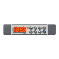
Model XW570K is microprocessor based controllers suitable for applications on medium or low temperature
refrigerating units. It must be connected by means of a two-wire cable ( 1mm) at a distance of up to 30 meters
to the keyboards T850. They are provided with six relay outputs to control compressor, defrost - which can be
either electrical or hot gas - the evaporator fans, the lights, the alarm and an auxiliary output. They are also
provided with three NTC probe inputs, one for temperature control, one to control the defrost end temperature of
the evaporator and the third, optional, for the display. There are two digital inputs (free contact) for the door
switch and configurable by parameter.
The standard TTL output allows the user to connect, by means of a TTL/RS485 external module, a ModBUS-
RTU compatible monitoring system and to programme the parameter list with the “Hot Key”. A 4÷20 mA output
to control evaporator or condenser fans and the direct serial output RS485 are available as options.
3. CONTROLLING LOADS
3.1 THE COMPRESSOR
The regulation is performed according to the temperature measured by the thermostat probe with a positive
differential from the set point: if the temperature increases and reaches set point plus differential the compressor
is started and then turned off when the temperature reaches the set point value again.
In case of fault in the thermostat probe the start and stop of the compressor are timed through parameters
“COn” and “COF”.
3.2 FAST FREEZING
When defrost is not in progress, it can be activated the keypad by holding the o key pressed for about 3
seconds. The compressor operates in continuous mode for the time set through the “CCt” parameter. The cycle
can be terminated before the end of the set time using the same activation key, o for about 3 seconds.
3.3 DEFROST
Three defrost modes are available through the “tdF” parameter: defrost with electrical heater, hot gas or
thermostatic defrost. The defrost interval is control by means of parameter “EdF”: (EdF = rtc) the defrost is made
in real time depending on the hours set in the parameters Ld1..Ld8 on workdays and in Sd1…Sd8 in holidays;
(EdF = in) the defrost is made every “IdF” time, (EdF=Sd) the interval “IdF” is calculate through Smart Defrost
algorithm (only when the compressor is ON and the evaporator temperature is bigger than “SdF” parameter).
At the end of defrost the drip time is controlled through the “Fdt” parameter.
3.4 CONTROL OF EVAPORATOR FANS
The fan control mode is selected by means of the “FnC” parameter:
C-n = running with the compressor, OFF during the defrost;
C-y = running with the compressor, ON during the defrost;
O-n = continuous mode, OFF during the defrost;
O-y = continuous mode, ON during the defrost;
An additional parameter “FSt” provides the setting of temperature, detected by the evaporator probe, above
which the fans are always OFF. This can be used to make sure circulation of air only if his temperature is lower
than set in “FSt”.
3.5 AUXILIARY OUTPUT
The auxiliary output is switch ON and OFF by means of the corresponding button on the keyboard.
4. KEYBOARD
To display and modify target set point; in programming mode it selects a parameter or confirm an
operation.
By holding it pressed for 3s when max or min temperature is displayed it will be erased.
By pressing it when the current time is displayed, it allows the User to re-set the current time and
three holidays.
To see the max. stored temperature; in programming mode it browses the parameter codes or
increases the displayed value. By holding it pressed for 3s the fast freezing cycle is started.
To see the min stored temperature; in programming mode it browses the parameter codes or
decreases the displayed value.
By holding it pressed for 3s the current time is displayed and it permits the User to enter Energy
saving, Defrost and Clock parameter menu.
By holding it pressed for 3s the defrost is started.
By pressing it when the current time is displayed, it allows the User to set defrost times.
Switch ON and OFF the cold room light.
By holding it pressed for 3s Energy Saving function is started or stopped.
By holding it pressed for 6s, the Holiday function is started or stopped.
By pressing it when the current time is displayed, it allows the User to set Energy Saving times.
Switch ON and OFF the auxiliary output.
Switch ON and OFF the instrument.
KEY COMBINATIONS
To lock and unlock the keyboard.
To enter the programming mode.
To exit the programming mode.
4.1 USE OF LEDS
Each LED function is described in the following table.
The compressor is running
- Programming Phase (flashing with LED )
- Anti-short cycle delay enabled
Programming Phase (flashing with LED )
The Fast Freezing cycle is enabled
- ALARM signal
- In “Pr2” indicates that the parameter is also present in “Pr1”
Function of the LEDs placed on the left top side of buttons:
Programming time is enabled
The Set point is displayed and it can be modified
The Manual Defrost is activated
Defrost times programming is enabled
The Energy Saving is enabled
Energy saving times programming is enabled
The Auxiliary output is ON
4.2 HOW TO SEE THE MIN TEMPERATURE
1. Press and release the n key.
2. The “Lo” message will be displayed followed by the minimum temperature recorded.
3. By pressing the n key or waiting for 5s the normal display will be restored.