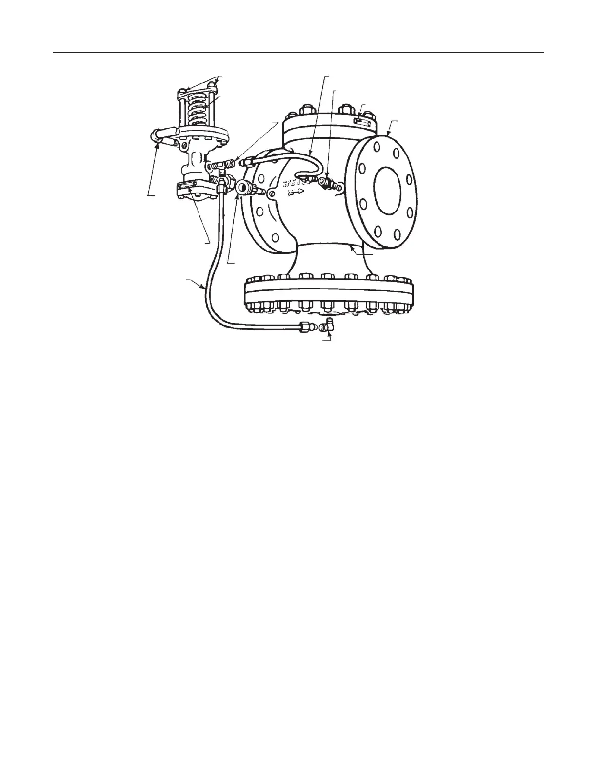
For Integral Mount Construction
1. Remove blind flange on pilot and mount on blind
flange of main valve using provided bolt.
2. Screw 4A bleed port fitting into the 1/8 in. pipe tap
at the outlet of the main valve body. Note bleed
orifice in this fitting is vital to operation of regulator.
3. Screw 8B tee into 1/8 in. pipe tap in pilot. Select
tap facing downstream.
4. Screw No. 5B elbow into 1/8 in. pipe tap on
underside of main valve diaphragm chamber.
5. Connect tubing bends as illustrated in Figure 3.
Figure 3. Mounting Pilot on Type E2 Main Valve
BLEEDPORT BEND
NO. 8B TEE
NO. 4A BLEEDPORT
NO. 5B OPEN ELBOW
RESTRICTION
BEND
ADJUSTING NUTS
ADJUSTING SPRING
SERIAL NO. PLATE
SERIAL NO. PLATE
1/4 IN.
CONTROL
PIPE
1/4 IN.
UNION
MAIN VALVE
TYPE E2
DO NOT INSULATE
BELOW THIS LINE
Control Pipe (Not required with
Type T14)
1. Use 1/4 in. pipe for this line which connect the
pilot diaphragm chamber to the desired point of
pressure control.
2. Take the control at a point of minimum turbulence.
Avoid control immediately at the valve outlet or
after a turn.
3. When the delivery pipe expands in size, select a
spot at least 4 pipe diameters beyond the point
of enlargement.
4. Pitch away from pilot to avoid erratic operation and
excessive fouling.
5. Eliminate water pockets.
6. Locate delivery pressure gage in control pipe to
show pressure actually reaching pilot diaphragm
5
Type E2

 Loading...


