Chapter 5 Input Characteristic 13
EC20 Series PLC User Manual
Chapter 5 Input Characteristic
5.1 User Ports Of Main Module
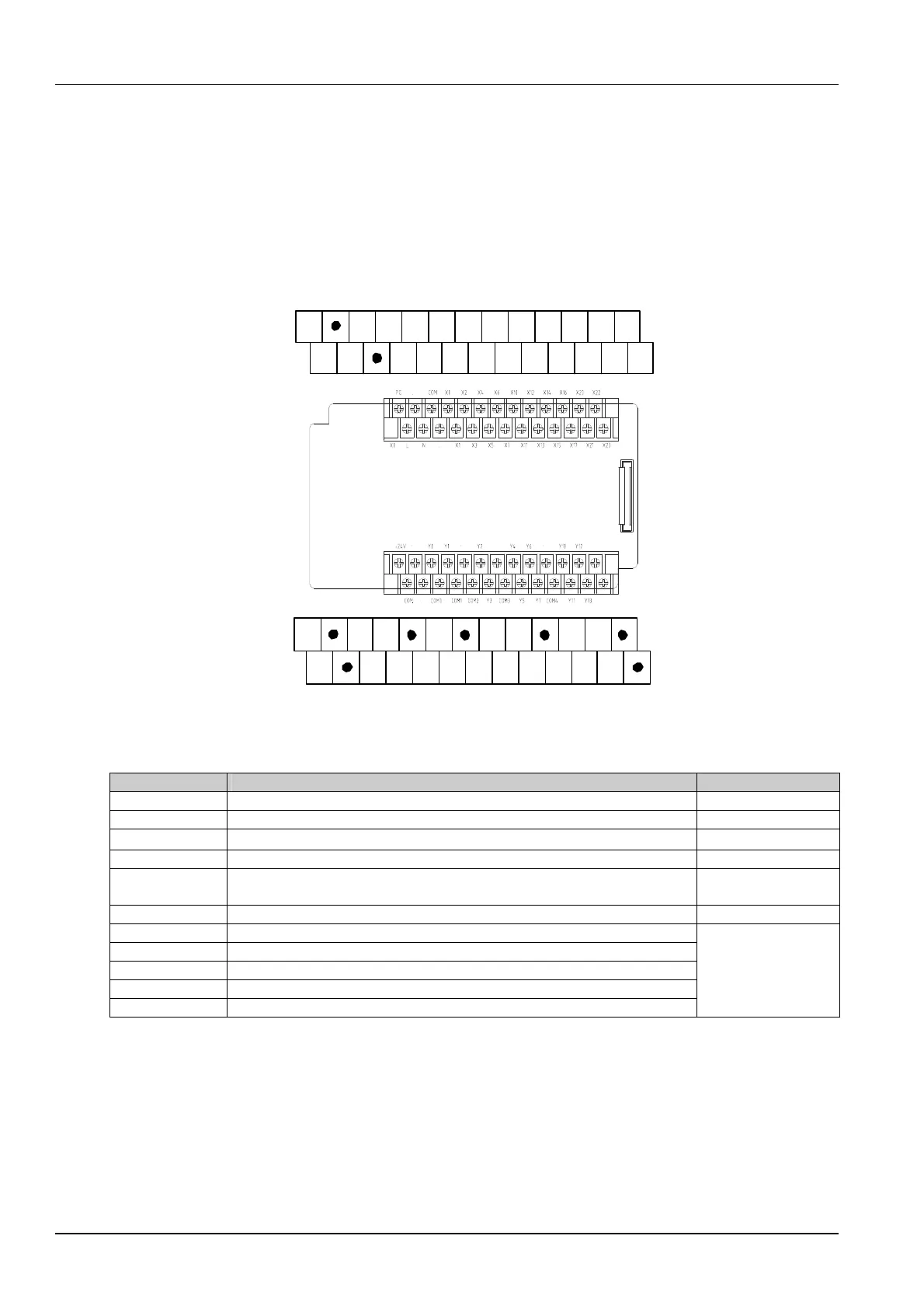
The outline and the ports of EC20-2012BR and EC20-2012BT are the same. Their port wirings are shown in Figure
5-1:
PG COM X0 X2 X4 X6 X10 X12 X14 X16 X20 X22
LX1X3X5X7 X21X11X13X15X17 X23
N
Wiring of EC20-2012BR and EC20-2012BT
+24V
Y0
Y2 Y4 Y6 Y10 Y12
Y1
Y13Y5 Y7 Y11COM
COM
0
COM
1
COM
2
Y3
COM
3
COM
4
Figure 5-1 The outline and the port of EC20-2012BR and EC20-2012BT
The pin definitions of EC20-2012BR and EC20-2012BT are listed in Table 5-1:
Table 5-1 Pin functions of EC20-2012BR and EC20-2012BT
Pin Function Note
L/N 220Vac AC power input port, L is live line, N is neutral line
PG Earth port
●
Null port, used for isolation and not wiring
X0~X23 User input signal ports, used together with COM can produce input signal
COM
Common port, it is the negative pole of the +24Vdc auxiliary power and the
common port of input as well. Two COMs connect inside the PLC
+24V The auxiliary power to user external equipment , used together with COM
Y0, COM0 Control output port, group 0
Y1, COM1 Control output port, group 1
Y2, Y3, COM2 Control output port, group 2
Y4~Y7, COM3 Control output port, group 3
Y10~Y13, COM4 Control output port, group 4
The COMx (COM0 ~
COM4) of each output
group are electrical
isolated one another
The outline, port layout and function definition of EC20-3232BR and EC20-3232BT are the same. The port layout is
shown in Figure 5-2:

 Loading...


