3
Factory Field
Code Parameter description and choices Min Max setting setting
L2 Output logic 0 3 1
0: Alarm & pump down. = normal; 1: Alarm = inverse, pump down. = normal
2: Alarm = normal, pump down. = inverse; 3: Alarm & pump down. = inverse
b1 Battery error management, 0 3 2 *
when battery is defective, see below:
Reset possibility after
Value Alarm display Alarm relay Valve recovery/replacement
0 - - Regulating -
1 Ab - Regulating -
2 Ab Signalling Fullyclose Auto
3 Ab(blinking) Signalling Fullyclose Manual
WARNING: When setting b1 to option 0 or 1, the user must ensure appropriate
safety precautions are in place to protect the system against damage caused by a
power failure.
Factory Field
Code Parameter description and choices Min Max setting setting
/6 Show decimal point; 0=yes, 1 = no 0 1 0
A6 Maximumdischargetemperature;°F 212 284 266
A7 Discharge temp. alarm delay; sec. 0 199 30
F2 Minimumcapacity;% 10 100 10
F3 Maximumcapacity;% 10 100 100
F6 ScrollValve,PWMcycletime;sec. 10 20 20
t3 Monitor discharge temperature sensor 0 1 0
0 = no, 1 = Yes
ru 0-10Vinputltering;0=off,1=on 0 1
* Min. and Max. setting values are dependent upon selected type of refrigerant.
LIST OF PARAMETERS IN SCROLLING SEQUENCE BY PRESSING BUTTON
Factory Field
Code Parameter description and choices Min Max setting setting
H5 Password 1 199 12
u0 System refrigerant 0 7 4
0=R22;1=R134a;2=R507;3=R404A;4=R407C;
5=R410A;6=R124;7=R744(subcriticalapplication)
uP Installed pressure sensor type 0 2 0
0=PT5-07M(forR22/R134a/R507/R404A/R407C/R124)
1=PT5-18M(forR410A)
2=PT5-30M(forR744,subcritical)
ut Installed valve type 1 3 2
1 = EX4; 2 = EX5; 3 = EX6
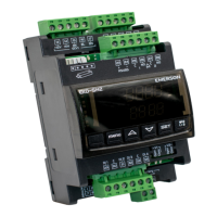
uu Startvalveopening(%) 10 100 50
u9 Start opening duration (second) 1 30 5
uL Low superheat alarm function 0 2 1
0=disable(foroodedevaporator)
1 = enable auto reset 2 = enable manual reset
Cut-out at 0.5K (if it maintains 1 min.); Cut-in immediately at 3K
u5 Superheatset-point(°F)
If uL enabled (auto or manual) 5.4 54 10.8
If uL disabled 0.9 54 10.8
u2 MOP function 0 1 1
0 = disable 1 = enable
u3 MOPset-point(°F)
saturation temperature
* * X
Factorysettingisaccordingtoselectedrefrigerant(u0):
+55°FforR22;+59°FforR134a:+45°FforR507
+45°FforR404A;+59°FforR407C;+59°FforR410A
+122°FforR124;+23°FforR744
┌┘5 Unitsconversion 0 1 0
0=°C,K,bar;1=°F,R,psig
(Psig values are divided by 10. Example: Display 12.5 is 125 psig)
┌┘1 Valuetoshow 0 4 0
0=Measuredsuperheat(°F);1=Measuredevaporatorpressure(psig)
2=Valveopening(%);3=Measuredcoil-outtemp.(°F)
4=Calculatedevaporatingtemperature(°F)fromthepressure
5=Compressorcapacityin%
u4 Superheat control mode 0 1 0
0 = Standard, 1 = Slow
uH High superheat alarm function 0 1 0
0 = disable, 1 = enable auto reset
uA High superheat alarm setpoint 16 40 30
ud High superheat alarm delay, min. 1 15 3
P2 Freezeprotectioncut-out,°F -40 104 -32
P3 Freezeprotectioncut-in,°F -35 109 37
P4 Freezeprotectionalarmfunction 0 2 0
0 = disable, 1 = enable auto-reset,
2 = enable manual reset
P5 Freezeprotectionalarmdelay,sec. 5 199 30
P6 Pump-down function
0 = disable, 1 = enable auto-reset 0 1 0
P7 Pump-down cut-out, psig -7.3 261.1 7.2
P8 Pump-down time delay, sec. 0 199 30
P9 Low pressure alarm function 0 2 0
0 = disable, 1 = enable auto-reset, 2 = enable manual reset
PA Low pressure alarm cut-out, psig -11.6 256.7 0
Pb Low pressure alarm delay, sec. 5 199 5
Pd Low pressure alarm cut-in, psig -7.3 261.1 4.3
LIST OF PARAMETERS IN SCROLLING SEQUENCE BY PRESSING BUTTON
SPECIAL FUNCTIONS
SpecialFunctionscanbeactivatedby:
• Pressandtogetherformorethan5seconds.
Aashing0isdisplayed.
• Pressoruntilthepasswordisdisplayed(default=12).
If password was changed, select the new password.
• PressSELtoconrmpassword
A0isdisplayedandtheSpecialFunctionmodeisactivated.
• Pressortoselectthefunction.Thenumberofspecialfunctionsis
dynamic and controller dependent. See list below.
0:Resetcontrollertofactorysettings(thisactionispossibleonlywhen
digital input is 0V i.e. open)
1: Displays the current TCP/IP address
2: Assign temporary 192.168.1.101 as TCP/IP address if EC3-D72 has
different address
• PressSEL to activate the function without leaving the special function
mode.
• PressPRG to activate the function and leave the special function mode.
Control (Valve)
Start-Up Behavior
(Parameter uu and u9)
PUMP DOWN FUNCTION (IFP6=1ANDL2=1)
Cooling Alarm
DemandStatus Condition PumpDownRelay
24V (ON) NO Activate
0V(OFF) NO Deactivatewhenpressuredropsbelow
P7 and after elapsed time P8
0V or 24V YES Deactivate instantaneously
START-UP
Start the system and check the superheat and operating conditions. The
EC3-D72 is fully functional without connected PC or keypad/display unit.
ECD-002.
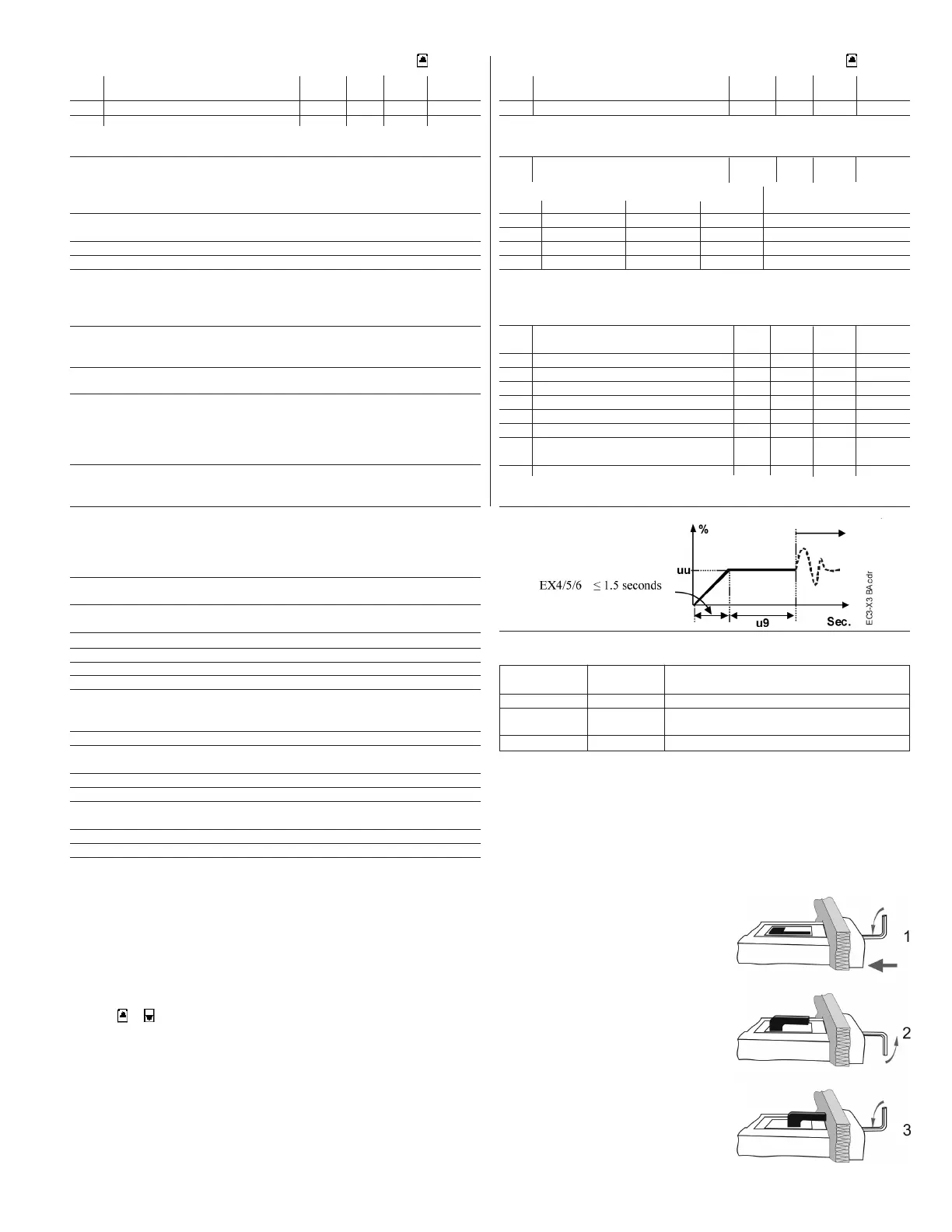
MOUNTING OF ECD-002
ECD-002 can be installed at any time also during operation.
• ECD-002canbemountedin
panels with 2.8 x 1.1 inch cutout
• Pushcontrollerintopanelcut-out.(1)
• Makesurethatmountinglugsare
ushwithoutsideofcontrollerhousing
• InsertAllenkeyintofrontpanelholesandturn
clockwise. Mounting lugs will turn and gradually
move towards panel (2)
• TurnAllenkeyuntilmountinglug
barely touches panel. Then move
other mounting lug to the same
position (3)
• Tightenbothsidesverycarefullyuntilkeypadissecured.
Do not over tighten as mounting lugs will break easily.

 Loading...