4
Requires manual
Alarm Related Alarm reset after
code Description parameter relay Valve What to do? resolving alarm
E0 Pressure transmitter error - Signalling Fully close Check wiring connection and measure the signal 4 to 20 mA No
E1 Coil-out temperature sensor error - Signalling Fully close Check wiring connection and measure the resistance of sensor No
E3 Discharge temp. - Signalling Regulating Check wiring connections and measure the resistance of
sensor error the sensor. Also check the status of the I/O configuration (t3)
AII EX4 – EX6 electrical connection error - Signalling - Check wiring connection and measure the resistance of winding No
Ab b1: 1 - Regulating Battery potentially does not have enough charge to close valve in case of main -
power supply interruption. May occur temporarily with new controllers or after
Ab Battery error b1: 2 Signalling Fully close long storage but should disappear when battery is charged sufficiently -
(allow 10hrs). If Ab remains active even when battery is charged, battery
Ab blinking b1: 3 Signalling Fully close may be defective and should be replaced. (Replacement kit: 097693). Yes
AE blinking Pump down action P6: 1 Signalling Already closed Allocate the source, which does not let suction pressure drops Yes
can not accomplished by Pumpdown below desired set-point
command
AF P4: 1 Signalling Fully close Check the system for cause of low pressure such as insufficient No
AF blinking Freeze protection P4: 2 Pumpdown load on evaporator Yes
deactivated
AL uL: 1 Signalling Fully close Check wiring connection and operation of valve No
AL blinking Low superheat (<0,5K) uL: 2 Pumpdown Yes
deactivated
AH High superheat uH: 1 Signalling Fully close Check the system No
Pumpdown
deactivated
AP Low pressure P9: 1 Signalling Fully close Check the system for cause of low pressure such as refrigerant loss No
AP blinking P9: 2 Pumpdown Yes
deactivated
dA High discharge temp. A6: alarm setpoint Signalling Fully close Check the system No
Pumpdown Fixed differential
deactivated = 10°C
Er Data error display – - - - Data send to the display is out of range. Check temperature and No
out of range pressure sensor.
ERROR/ALARM HANDLING
Note: When multiple alarms occur, the highest priority alarm is dis-
played until being cleared, then the next highest alarm is displayed
until all alarms are cleared. Only then will parameters be shown again.
Message
--- No data to display
Thedisplaywillshowan“---”atstartupandwhennodataisbeingsenttotheECD-002
CHECKING SYSTEM OPERATING CONDITIONS USING LOCAL DISPLAY/KEYPAD ECD-002
Thedisplaywillshowforonesecondthenumericalidentierofthedata
(see┌┘1parameter)andthentheselecteddata.After5minutes,the
displaywillreturntothevalueselectedbyparameter┌┘1.
The data to be permanently shown on the display can be selected by
theuser(parameter┌┘1).Itispossibletotemporarilydisplaythese
values. However this function is not available in an alarm condition.
SERVICE/TROUBLESHOOTING
SYMPTOM CAUSE ACTION
Operating superheat is several degrees Incorrect signal from pressure 1- Check the sensors
higher or lower than set-point or temperature sensors 2- Make sure ECN-N60 temperature sensor is used
3-Foroptimumaccuracy,pleaseuse:
PT5-07MforR22/R134a/R507/R404A/R407C/R124
PT5-18MforR410A
PT5-30MforR744
4- Make sure the sensor cables are not installed along with other
high voltage cables
Operating superheat is too low; 1- Incorrect wiring of ECV 1- Check the wiring
i.e. compressor wet running 2- Defective sensors 2- Check the sensor
Valve is not fully closed 1- The cooling demand digital 1- Valve is shut off only when the digital input is turned off (0V)
input is ON (24V)
2- Wrong ECV selected 2- Check the setting of parameter ut
Unstable superheat (hunting) Evaporator is designed to operate Increase the superheat set-point to a higher value; if system is stable,
at higher superheat start decreasing gradually, checking each time for a stable control
Valve opens when EC3 commands Wrong wiring between EC3-D72 Check the wiring and obey the color coding: white/black, blue/brown
to close and vice versa and valve
Superheat set-point is shifting after several Stepper motor driven valves Do not apply permanent 24V digital input. Interrupt digital input once
monthsofuninterruptedoperationor requiresynchronization everyweekfor5secondsifcompressorneverstops.Thishasthe
permanent jumper of 24V digital input effect of referencing the valve to the fully closed position
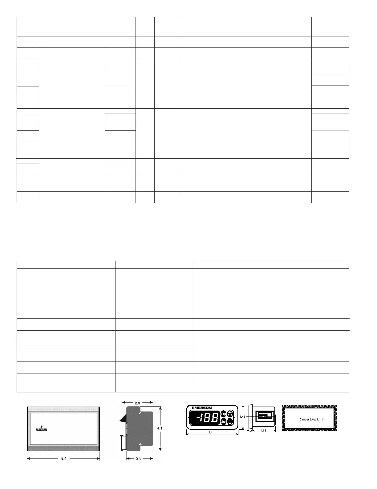
DIMENSIONS (IN INCHES)
EC3-D72
ECD-002
EmersonClimate.com/FlowControls
Technical Support: 1-866-625-8416
PA-00368 (06/13) Emerson is a trademark of Emerson Electric Co. ©2013 Emerson Climate Technologies, Inc. All rights reserved.

 Loading...