Product Identication and Marking
Hazardous Locations
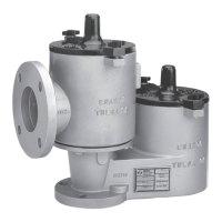
Fisher™ spring-loaded pressure/vacuum relief valves
are available with outer housings of carbon steel,
stainless steel or aluminum, as indicated in Figure 5.
Nameplate
A nameplate is attached to the valve and contains the
following information:
• Model Number – Ex. 860- 3X4-4211
• Conn. Flange Size and Rating – Ex. 3 in.
• Serial Number
• Tag Number (Optional)
• Notied Body Number – Ex. 2460
• Cat. No. (Category Number) –
Ex. -
Category 1 - Stainless steel, Carbon steel or
Coated Aluminum vents
Category 2 - Uncoated Aluminum vents
• Date – Date of Manufacture
• Certicate – Ex. PRESAFE 17 ATEX 10273X
• Pressure
- Setting – Ex. Z4.0
- Flow Rate SCFH (Air) – Ex. 55000
• Vacuum
- Setting – Ex. Z0.5
- Flow Rate SCFH (Air) – Ex. 25000
Principle of Operation
The Fisher spring-loaded pressure/vacuum relief valve The Fisher spring-loaded pressure/vacuum relief valve
maintains a tight seal, until system pressure or vacuum maintains a tight seal, until system pressure or vacuum
exceeds the set pressure of the valve. Set pressure is exceeds the set pressure of the valve. Set pressure is
established by the force of a spring or a set of multiple established by the force of a spring or a set of multiple
springs acting on the valve pallet. When the system springs acting on the valve pallet. When the system
pressure is above the set pressure, the pallet starts to pressure is above the set pressure, the pallet starts to
lift, breaking the seal between the seat and pallet. This lift, breaking the seal between the seat and pallet. This
allows vapors to pass through the valve orice and allows vapors to pass through the valve orice and
relieve pressure buildup. The valve reseals upon relief relieve pressure buildup. The valve reseals upon relief
and remains sealed.and remains sealed.
Relieving vapors near the set pressure in a continuous
manner may cause the pallet to utter or oscillate inside
the valve chamber. This is common to products of this
model. Operating the valve with utter or oscillation may
cause premature valve damage or wear over time. The
utter zone typically begins at the set point and ends at
the ow rate associated with 10% overpressure. The
Fisher Valve Sizing Program displays the utter zone.
Contact your local Sales Oce with any questions or
additional assistance.
Figure 5. ATEX Certified Markings
OUTER HOUSING OF STAINLESS STEEL,
CARBON STEEL OR COATED ALUMINUM
OUTER HOUSING OF UNCOATED ALUMINUM
II 1 G Ex h IIC T6 Ga
II 2 G Ex h IIC T6 Gb
4
Enardo 860 and 960 Series
Outside North America Only
 Loading...