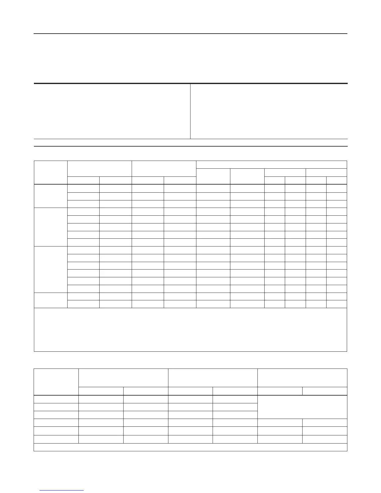
TYPE
MAXIMUM INLET PRESSURE
MAXIMUM EMERGENCY
OUTLET PRESSURE OR MAXIMUM
EMERGENCY SENSE PRESSURE
(1)
MAXIMUM BLEED (EXHAUST) PRESSURE
FOR MONITOR PILOTS
psig bar psig bar psig bar
161 1500 103 1200 82.7
- - - -
161AY 150 10.3 150 10.3
161EB and 161EBH 1500 103 1200 82.7
161M 1500 103 1200 82.7 1500 103
161AYM or 161AYW 150 10.3 150 10.3 150 10.3
161EBM and 161EBHM 1500 103 1200 82.7 1500 103
1. Maximum pressure to prevent the casings from bursting during abnormal operation (leaking to atmosphere and internal parts damage may occur).
PILOT TYPE
OUTLET (CONTROL)
PRESSURE RANGE
PROPORTIONAL
BAND
(1)(2)(3)
PILOT CONTROL SPRING INFORMATION
Part Numbers Color Code
Wire Diameter Free Length
psig bar psig bar In. mm In. mm
161 or 161M
5 to 15 0.34 to 1.03 2 0.14 1E392527022 Yellow 0.148 3.76 2.00 50.8
10 to 125 0.69 to 8.62 2 0.14 1K748527202 Red 0.192 4.88 2.19 55.6
120 to 300 8.3 to 20.7 6 0.41 15A9258X012 Green 0.243 6.17 1.88 47.8
161AY, 161AYM
or 161AYW
6 to 15 in. w.c.
(4)
15 to 37 mbar
(4)
1 in. w.c 2 mbar 1B653927022 Olive Green 0.105 2.67 3.75 95.2
0.5 to 1.2
(5)
0.03 to 0.08
(5)
1 in. w.c 2 mbar 1B537027052 Yellow 0.114 2.90 4.31 109
1.2 to 2.5
(6)
0.08 to 0.17
(6)
0.5 0.03 1B537127022 Green 0.156 3.96 4.06 103
2.5 to 4.5 0.17 to 0.31 0.5 0.03 1B537227022 Light Blue 0.187 4.75 3.94 100
4.5 to 7 0.31 to 0.48 0.5 0.03 1B537327052 Black 0.218 5.54 3.98 101
161EB or
161EBM
5 to 15 0.34 to 1.03 0.5 0.03 17B1260X012 White 0.120 3.05 3.75 95.2
10 to 40 0.69 to 2.76 0.5 0.03 17B1262X012 Yellow 0.148 3.76 3.75 95.2
30 to 75 2.07 to 5.17 0.6 0.04 17B1259X012 Black 0.187 4.75 4.00 102
70 to 140 4.83 to 9.65 1.3 0.09 17B1261X012 Green 0.225 5.71 3.70 94.0
130 to 200 8.96 to 13.8 1.5 0.10 17B1263X012 Blue 0.262 6.66 3.85 97.8
200 to 350 13.8 to 24.1 3 0.21 17B1264X012 Red 0.294 7.47 4.22 107
161EBH or
161EBHM
250 to 450 17.2 to 31.0 3.5 0.24
(7)
17B1263X012 Blue 0.262 6.66 3.85 97.8
400 to 700 27.6 to 48.2 7 0.48
(7)
17B1264X012 Red 0.294 7.47 4.22 107
1. Proportional band includes outlet pressure drop plus hysteresis (friction), but does not include lockup.
2. Proportional band was determined with a pressure drop ranging from 50 to 150 psig / 3.4 to 10.3 bar. Approximately double the proportional band if the pressure drop is less than
50 psig / 3.4 bar.
3. With Type 112 restrictor set on 2.
4. The spring ranges for the Type 161AYW is 3 to 12 in. w.c. / 7.5 to 30 mbar.
5. The spring ranges for the Type 161AYW is 11 to 25 in. w.c. / 27 to 62 mbar.
6. The spring ranges for the Type 161AYW is 0.9 to 2.5 psig / 0.06 to 0.17 bar.
7. Proportional band was determined with a pressure drop ranging from 100 to 300 psig / 6.9 to 20.7 bar. Approximately double the proportional band if the pressure drop is less than
100 psi / 6.9 bar
Table 1. Outlet (Control) Pressure Ranges, Proportional Bands and Pilot Control Spring Information
Table 2. Pilot Pressure Ratings
Specications
The Specications section lists pressure limitations and other specications for all models of 161 Series pilots.
Please note that the pilot control spring range is marked on the spring case of 161 and 161EB Series pilots and
on the nameplate of 161AY Series pilots.
Outlet (Control) Pressure Ranges
See Table 1
Proportional Bands
See Table 1
Maximum Inlet Pressure
(1)
See Table 2
Pilot Flow Coefcients
See Table 3
Options
Type 252 Pilot supply lter
Pilot Sping Case Vent
1/4 NPT (internal)
1. The pressure/temperature limits in this Instruction Manual and any applicable standard or code limitation should not be exceeded.
2
161 Series

 Loading...


