spring case (key 2, Figures 4 through 6 or key 3,
Figure 7) to increase the downstream pressure. Turn
the adjusting screw out of the spring case to decrease
the downstream pressure.
Shutdown
CAUTION
If pilot supply pressure is shut down
rst, the downstream system may be
subjected to full inlet pressure.
1. If the pilot setting must be disturbed, be sure to
keep some tension on the spring. This will prevent
trapping inlet pressure during blowdown.
2. Slo wly close the valves in the following order:
a. Inlet block valve
b. Outlet block valve
c. Control line valve(s), if used.
3. Open the vent valves to depressurize the system.
Maintenance
Pilot parts are subject to normal wear and must be
inspected and replaced as necessary. The frequency
of inspection and replacement of parts depends upon
the severity of service conditions or the requirements
of local, state and federal regulations. Due to the
care Emerson
takes in meeting all manufacturing
requirements (heat treating, dimensional tolerances,
etc.), use only replacement parts manufactured or
furnished by Emerson.
All O-rings, gaskets and seals should be lubricated
with a good grade of general-purpose grease and
installed gently rather than forced into position. Be
certain that the nameplates are updated to accurately
indicate any eld changes in equipment, materials,
service conditions or pressure settings.
!
WARNING
To avoid personal injury resulting from
sudden release of pressure, isolate the
pilot from all pressure and cautiously
release trapped pressure from the pilot
before attempting disassembly.
Note
This procedure covers all 161EB Series
pilots. Types 161EB and 161EBM are
rated for outlet pressure settings over
200 psig / 13.8 bar. Types 161EB and
161EBM pilots rated for outlet pressure
settings under 200 psig / 13.8 bar do not
require a diaphragm limiter.
161 and 161EB Series Pilots
(Figures 4 through 6)
Trim Parts
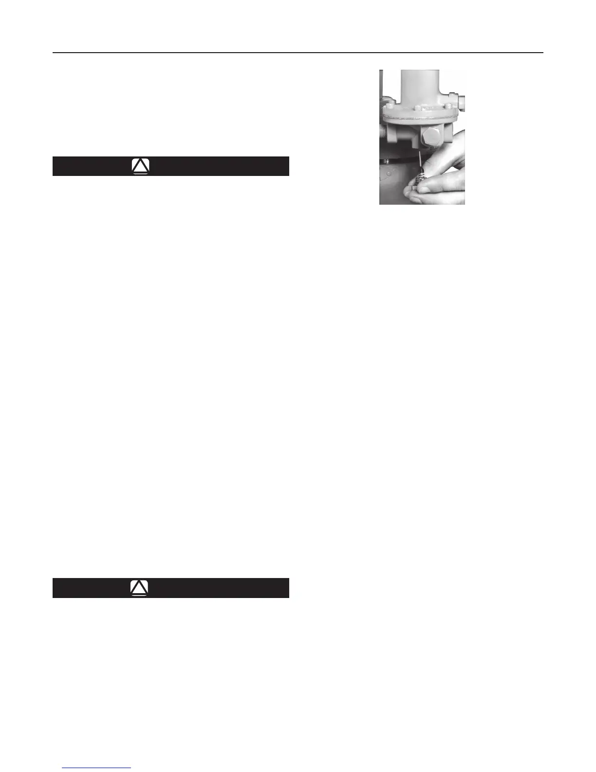
1. As shown in Figure 2, remove the body plug
(key 3) to let the plug spring (key 6) and valve plug
(key 4) drop freely from the body.
2. Inspect the removed parts and body plug O-ring
(key 15), replace as necessary and make sure the
plug seating surfaces are free from debris.
3. Sparingly apply lubricant to the body plug O-ring
(key 15) and the threads of the body plug (key 3).
Install the body plug O-ring over the body plug.
4. Stack the plug spring (key 6) and valve plug
(key 4) on the body plug (key 3). Install the body
plug with stacked parts into the body (key 1).
Diaphragm Parts
1. Remove the closing cap (key 16), loosen the
locknut (key 12) and back out the adjusting screw
(key 11) until compression is removed from the
control spring (key 9).
2. Remove the machine screws (key 13, not shown)
and separate the spring case (key 2) from the
body (key 1). Remove the control spring seat
Figure 2. 161EB Series Pilot Trim Removal/Installation
W4570-1
5
161 Series

 Loading...


