Instruction Manual
D103292X012
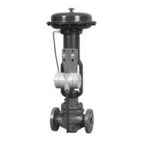
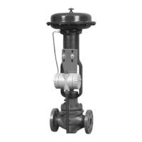
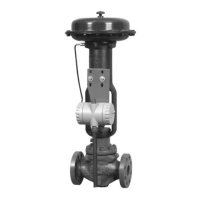
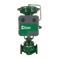
C1 Controllers and Transmitters
March 2017
3
Table 1. Specifications
Available Configurations
See table 2
Input Signal
Type: J Gauge pressure, J vacuum, J compound
pressure, or J differential pressure of a liquid or gas
Limits: See table 3 or 4
Output Signal
Proportional-Only or Proportional-Plus-Reset
Controllers and Transmitters:
J 0.2 to 1.0 bar (3 to 15 psig) or
J 0.4 to 2.0 bar (6 to 30 psig) pneumatic pressure
signal
Differential Gap Controllers:
J 0 and 1.4 bar (0 and 20 psig) or
J 0 and 2.4 bar (0 and 35 psig) pneumatic pressure
signal
Action: Control action is field reversible between
J direct (increasing sensed pressure produces
increasing output signal) and J reverse (increasing
sensed pressure produces decreasing output signal).
Supply Pressure Requirements
(1)
See table 5
Supply Pressure Medium
Air or Natural Gas
Supply medium must be clean, dry and non-corrosive
Per ISA Standard 7.0.01
A maximum 40 micrometer particle size in the air
system is acceptable. Further filtration down to 5
micrometer particle size is recommended. Lubricant
content is not to exceed 1 ppm weight (w/w) or
volume (v/v) basis. Condensation in the air supply
should be minimized
Per ISO 8573-1
Maximum particle density size: Class 7
Oil content: Class 3
Pressure Dew Point: Class 3 or at least 10°C less than
the lowest ambient temperature expected
Steady-State Air Consumption
(2)(3)
0.2 to 1.0 bar (3 to 15 psig): 0.08 normal m
3
/hour
(3 scfh)
0.4 to 2.0 bar (6 to 30 psig): 0.12 normal m
3
/hour
(4.5 scfh)
Supply and Output Connections
1/4 NPT internal
Common Signal Pressure Conversions
See table 6
Proportional Band Adjustment
For Proportional-Only Controllers: Full output
pressure change adjustable from J 2% to 100% of the
sensing element range for 0.2 to 1.0 bar (3 to 15 psig)
or J 4% to 100% of the sensing element range for 0.4
to 2.0 bar (6 to 30 psig)
For Proportional-Plus-Reset Controllers: Full output
pressure change adjustable from J 3% to 100% of the
sensing element range for 0.2 to 1.0 bar (3 to 15
psig), or J 6% to 100% of the sensing element range
for 0.4 to 2.0 bar (6 to 30 psig)
Differential Gap Adjustment
For Differential Gap Controllers:
Full output pressure change adjustable from
15% to 100% of sensing element range
Reset Adjustment
For Proportional-Plus-Reset Controllers: Adjustable
from 0.01 to 74 minutes per repeat (100 to 0.01
repeats per minute)
Zero Adjustment (Transmitters Only)
Continuously adjustable to position span of less than
100% anywhere within the sensing element range
Span Adjustment (Transmitters Only)
Full output pressure change adjustable from 6 to
100% of sensing element range
Performance
Repeatability: 0.5% of sensing element range
Deadband (Except Differential Gap Controllers)
(4)
:
0.1% of sensing element range
Typical Frequency Response at 100% Proportional
Band
Output to Actuator: 0.7 Hz and 110 degree phase shift
with 1850 cm
3
(113 inches
3
) volume, actuator at
mid-stroke
Output to Positioner Bellows: 9 Hz and 130 degree
phase shift with 0.2 to 1.0 bar (3 to 15 psig) output to
33 cm
3
(2 inches
3
) bellows
−continued−
 Loading...