Instruction Manual
D103292X012
C1 Controllers and Transmitters
March 2017
5
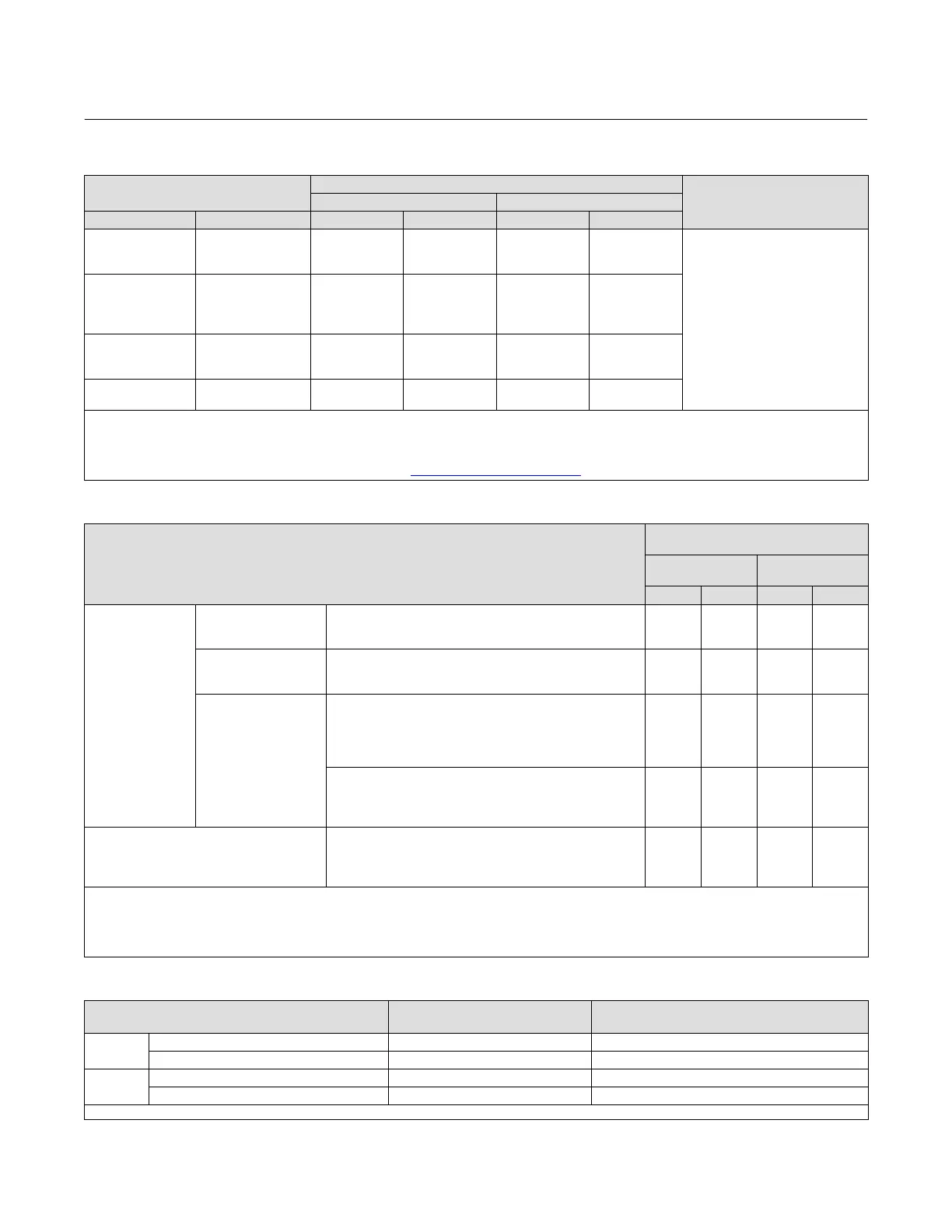
Table 3. Bourdon Tube Pressure Range and Materials
PRESSURE RANGES
(1,2)
MAXIMUM ALLOWABLE STATIC PRESSURE LIMITS
(3)
MATERIAL
(5)
Standard With Optional Travel Stop
(4)
Bar Psig Bar Psig Bar Psig
0 to 2.0
0 to 4.0
0 to 7.0
0 to 30
0 to 60
0 to 100
2.0
4.0
7.0
30
60
100
3.3
6.6
11
48
96
160
316 stainless steel
0 to 14
0 to 20
0 to 40
0 to 70
0 to 200
0 to 300
0 to 600
0 to 1000
14
20
40
70
200
300
600
1000
19
29
50
83
280
420
720
1200
0 to 100
0 to 200
0 to 350
0 to 1500
0 to 3000
0 to 5000
100
200
350
1500
3000
5000
115
230
380
1650
3300
5500
0 to 550
0 to 700
0 to 8000
0 to 10.000
550
700
8000
10,000
550
700
8000
10,000
1. If the process can trip to a pressure outside of the operating range of the sensing element, a commercially available device, such as an overpressure protector, may be used to protect
against pressure surges and pulsations.
2. Range marked on Bourdon tube may be in kPa (1 bar = 100 kPa)
3. Bourdon tube may be pressurized to limit shown without permanent zero shift.
4. With travel stop set at 110% of the range.
5. Bourdon tubes are also available in NACE compliant material. Contact your Emerson Automation Solutions sales office
for additional information.
Table 4. Bellows Pressure Ranges and Materials
PRESSURE RANGES
(1)
MAXIMUM ALLOWABLE STATIC
PRESSURE LIMITS
(2)
Brass
Construction
Stainless Steel
Construction
Bar Psig Bar Psig
Gauge Pressure
Vacuum
0 to 150 mbar (0 to 60 inch wc)
0 to 340 mbar (0 to 10 inch Hg)
0 to 1.0 bar (0 to 30 inch Hg)
1.4
2.8
2.8
20
40
40
---
---
6.9
---
---
100
Compound Pressure
75 mbar vac. to 75 mbar (30 inch wc vac. to 30 inch wc)
500 mbar vac. to 500 mbar (15 inch Hg vac. to 7.5 psig)
1.0 bar vac. to 1.0 bar (30 inch Hg vac. to 15 psig)
1.4
2.8
2.8
20
40
40
---
6.9
6.9
---
100
100
Positive pressure
0 to 150 mbar (0 to 60 inch wc)
0 to 250 mbar
(3)
(0 to 100 inch wc)
0 to 350 mbar
(4)
(0 to 140 inch wc)
0 to 0.35 bar (0 to 5 psig)
0 to 0.5 bar (0 to 7.5 psig)
1.4
1.4
2.8
2.8
2.8
20
20
40
40
40
---
---
---
---
---
---
---
---
---
---
0 to 0.7 bar (0 to 10 psig)
0 to 1.0 bar (0 to 15 psig)
0 to 1.4 bar (0 to 20 psig)
0 to 2.0 bar (0 to 30 psig)
2.8
2.8
2.8
2.8
40
40
40
40
---
6.9
---
6.9
---
100
---
100
Differential Pressure
(5)
0 to 300 mbar (0 to 80 inch wc)
0 to 0.7 bar (0 to 10 psi)
0 to 1.4 bar (0 to 20 psi)
0 to 2.0 bar (0 to 30 psi)
1.4
2.8
2.8
---
20
40
40
---
---
---
---
6.9
---
---
---
100
1. If the process can trip to a pressure outside of the operating range of the sensing element, a commercially available device, such as an overpressure protector, may be used to protect
against pressure surges and pulsations.
2. Bellows may be pressured to limit shown without permanent zero shift.
3. Transmitter only.
4. Except transmitter.
5. The overrange limit for these sensing elements is a differential pressure equal to the maximum allowable static pressure limit.
Table 5. Supply Pressure Requirements
Output Signal Range
Normal Operating Supply
Pressure
(1)
Maximum Allowable Supply Pressure To Prevent
Internal Part Damage
Bar
0.2 to 1.0 or 0 and 1.4 (differential gap) 1.4 2.8
0.4 to 2.0 or 0 and 2.4 (differential gap) 2.4 2.8
Psig
3 to 15 or 0 and 20 (differential gap) 20 40
6 to 30 or 0 and 35 (differential gap) 35 40
1. If this pressure is exceeded, control may be impaired.
 Loading...