Instruction Manual
D103292X012
C1 Controllers and Transmitters
March 2017
47
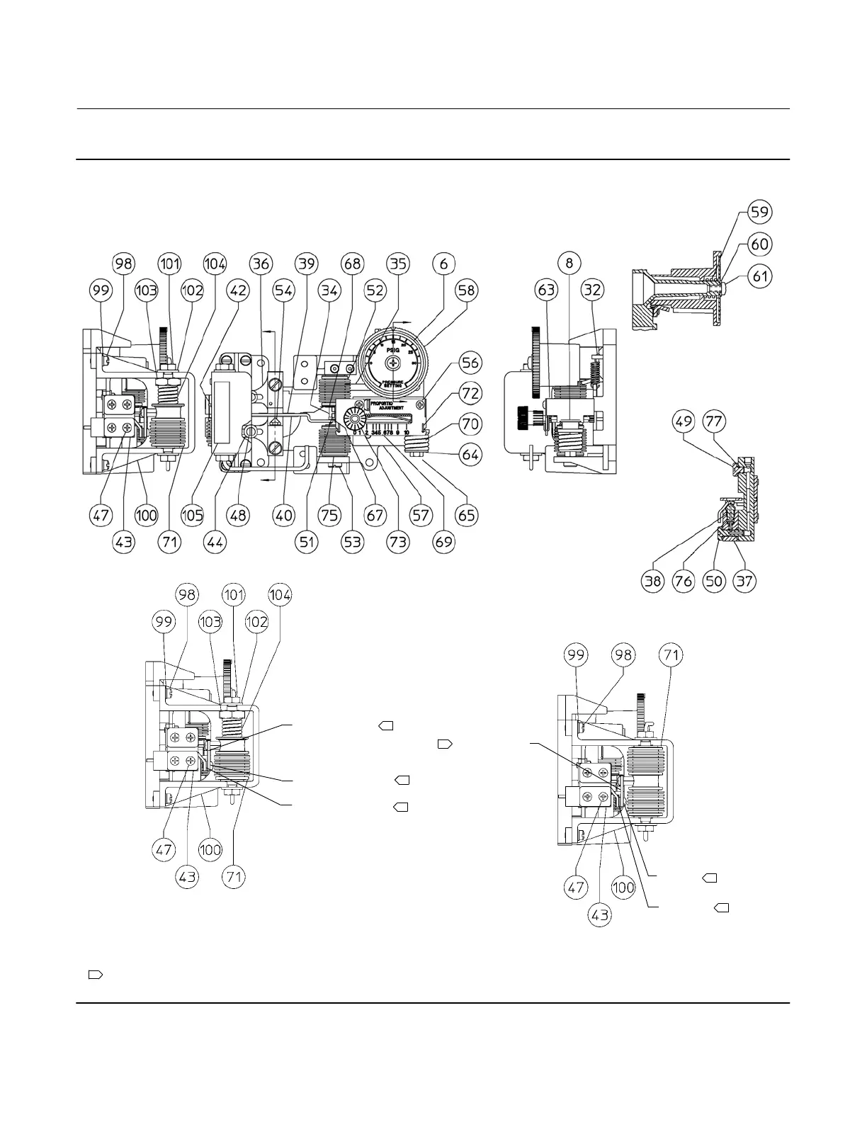
Figure 25. Controller Subassembly with Either Gauge-Pressure Bellows or Differential-Pressure Bellows Sensing
Element
SCREW (KEY 71K)
LINK (KEY 71M)
SCREW
(KEY 71K)
BEARING
(KEY 71L)
LINK (KEY 71M)
BEARING (KEY 71L)
SECTION A-A
A
A
SIDE VIEW OF SUBASSEMBLY
WITH GAUGE-PRESSURE
BELLOWS SENSING ELEMENT
SIDE VIEW OF SUBASSEMBLY WITH DIFFERENTIAL
PRESSURE BELLOWS SENSING ELEMENT
NOTES:
KEYS 33, 46 AND 74 ARE NOT SHOWN
KEY 52 IS FEEDBACK BELLOWS
KEYS 71K, 71L, & 71M ARE PART OF THE BELLOWS ASSEMBLY (KEY 71)
1
1
1
1
1
B
B
SECTION B-B
1
1
GE35161-A
GE34735-C
 Loading...