Instruction Manual
D103292X012
C1 Controllers and Transmitters
March 2017
46
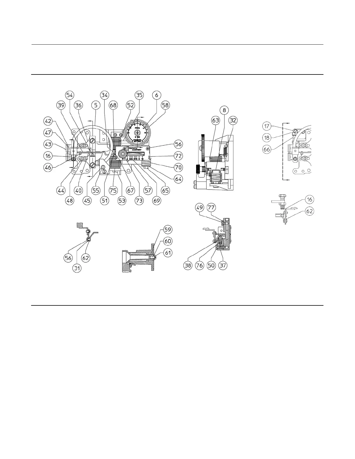
Figure 24. Controller Subassembly with Bourdon Tube Sensing Element
BOURDON TUBE TRAVEL
STOP SUBASSEMBLY
NOTE:
KEYS 33 AND 74 ARE NOT SHOWN
A
A
B
A
A
C
SECTION A-A
SECTION B-B
VIEW A-A
GE26600-C
GE33918-A
B
C
SECTION C-C
Key Description
71* Differential-Pressure Bellows (input)
Brass
0-200 mbar (0-80 inches wc)
0-0.7 bar (0-10 psi)
0-1.4 bar (0-20 psi)
Stainless steel,
0-2.0 bar (0-30 psi)
71K Machine Screw
(4)
, steel pl
bellows sensing instruments only (2 req'd)
71L* Bearing
(4)
bellows sensing instruments only (2 req'd)
71M* Link
(4)
bellows sensing instruments only
Key Description
72* Lock Spring, 304L SST
73 Proportional Band Adjustment Knob, steel/PPS
74 Machine Screw
(1)
, 18-8 SST (2 req'd)
75* Gasket
(1)
Std Temp, chloroprene (2 req'd)
High Temp, silicone (2 req'd)
76* Nozzle O-Ring
(1)
,
Std Temp, nitrile
High Temp, fluorocarbon
*Recommended spare parts
1. This part is included in the Controller Repair Kit.
keys 101, 102, and 103 if you do not have them.
4. This part is part of the bellows assembly, key 71.
 Loading...