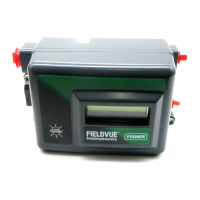
DVC2000 Digital Valve Controller
July 2009
6-8
CIRCUIT
UNDER
TEST
VOLTMETER
MILLIAMMETER
1 KILOHM POTENTIOMETER
A6192-1/IL
Figure 6-4. Voltage Test Schematic
Checking Voltage Available
WARNING
Personal injury or property damage
caused by fire or explosion may occur
it this test is attempted in any area
which contains a potentially explosive
atmosphere or has been classified as
hazardous.
To check the Voltage Available at the instrument,
perform the following:
1. Disconnect the field wiring from the control system
and connect equipment as shown in figure 6-4 to the
control system terminals.”
2. Set the control system to provide maximum output
current.
3. Set the resistance of the 1 kilOhm potentiometer
shown in figure 6-4 to zero.
4. Record the current shown on the milliammeter.
5. Adjust the resistance of the 1 kilOhm potentiometer
until the voltage read on the voltmeter is 9.0 Volts.
6. Record the current shown on the milliammeter.
7. If the current recorded in step 6 is the same as that
recorded in step 4 (± 0.08 mA), the voltage available is
adequate.
6

 Loading...


