DO Function Block
March 2006
5-149
considered a logic 1. With this option disabled, OUT_D
[9] is a direct copy of SP_D [8]. The readback value is
processed through the Invert option to become PV_D
[7]. The Use PV for BKCAL_OUT option specifies that
BKCAL _OUT equal the value of the process variable
(PV_D [7]) instead of the set point (SP_D [8]). If you
do not enable this option, BKCAL_OUT will equal
SP_D [8].
Output Block PV Status
The Output Block PV Status is determined by the
enabled status of the Resource Block parameter
FEATURE_SEL [18], the Transducer Block mode, and
enabled Active PlantWeb alarms. Refer to table 5-1.
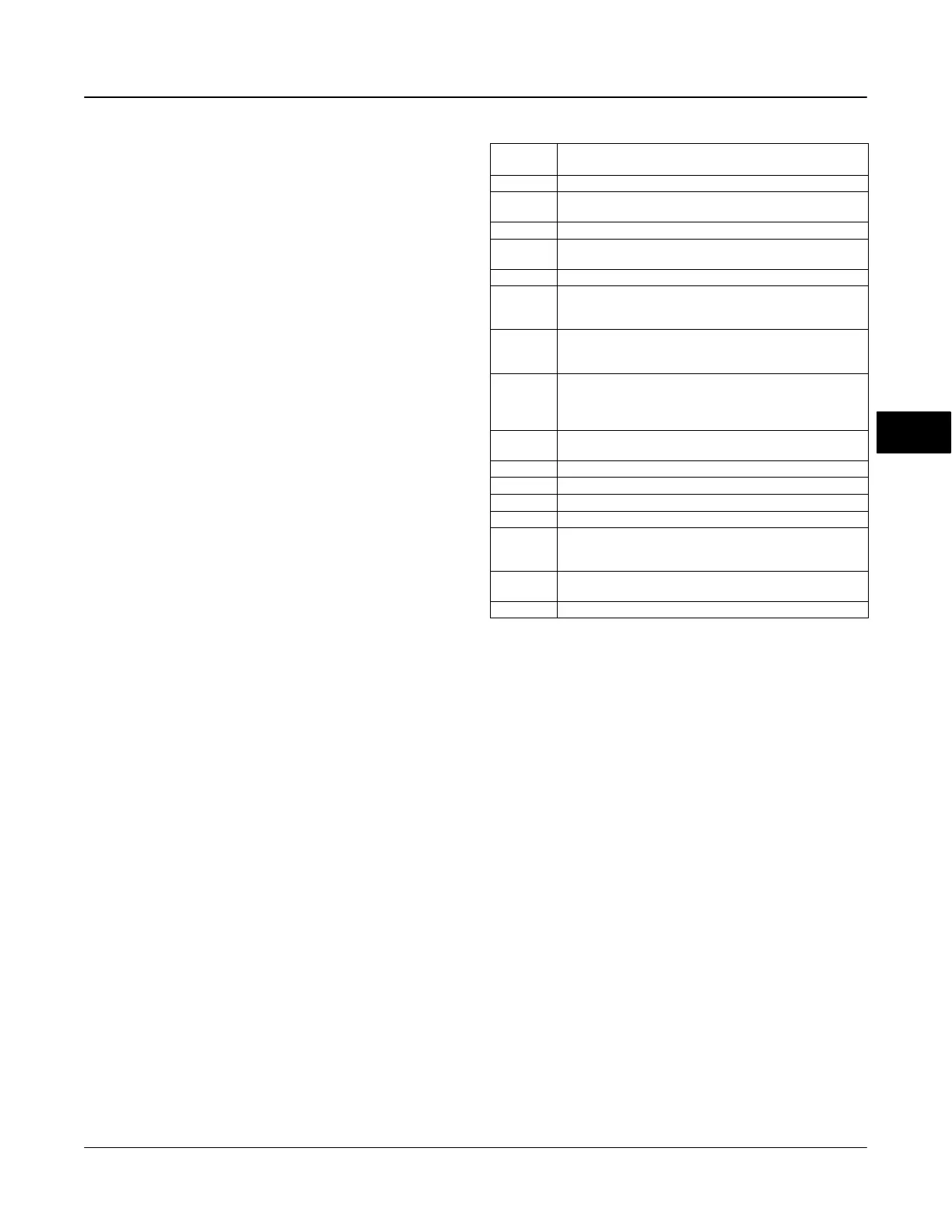
Block Errors
Table 5-70 lists conditions reported in the
BLOCK_ERR [6] parameter. Conditions in italics are
not applicable for the DO block and are provided only
for your reference.
Action on Fault Detection
Fault State is caused by one of three sources: A
status pertaining to CAS, A status pertaining to RCAS,
or SET_FSTATE [29] in the resource block. To
implement Fault State, configure the following
parameters:
IO_OPTS [14]: Determines the action OUT_D [9] will
take upon a fault state. If the IO_OPTS [14] “Fault
State to Value” is not selected, then OUT_D [9] holds
its last position when Fault State is set. If “Fault State
to Value” is selected, OUT_D [9] goes to the
FSTATE_VAL_D [20] value when Fault State is set.
FSTATE_TIME [19]: The length of time, in seconds,
that the DO block will wait to set Fault State. When
Table 5-70. BLOCK_ERR Conditions
Condition
Number
Condition Name and Description
0 Other (N/A)
1
Block Configuration Error - SHED_OPT or CHANNEL set to
0 (uninitialized)
2 Link Configuration Error (N/A)
3
Simulate active - Simulation is enabled and the block is using
a simulated value in its execution.
4 Local Override - Device in fault state. Actual mode LO.
5
Device Fault State Set - DO block in fault state after
FSTATE_TIME because of Bad status or IFS substatus on
CAS_IN_D or Resource block commanded fault state.
6
Device Needs Maintenance Soon - Indicates a Maintenance
PlantWeb Alert condition is active if Block Error Reporting is
enabled. See page 5-39.
7
Input failure/process variable has Bad status - PV has bad
status and Feature Select in the Resource block has the Out
Readback bit set or the transducer block mode is Out of
Service.
8
Output failure - PV has bad status or the transducer block
mode is Out of Service.
9 Memory Failure (N/A)
10 Lost Static Data (N/A)
11 Lost NV Data (N/A)
12 Readback Check Failed (N/A)
13
Device Needs Maintenance Now - Indicates Failed
PlantWeb Alert condition is active if Block Error Reporting is
enabled. See page 5-39.
14
Power Up - This condition exists after power up until actual
mode is not Out of Service.
15 Out of Service - The block is in Out of Service (OOS) mode.
Fault State is set, the OUT_D [9] value goes to either
the FSTATE_VAL_D [20] value or holds its last
position, depending on I/O_OPTS [14]. When the
block has a target mode of CAS, a fault condition will
be detected if the CAS_IN_D [17] has a BAD status or
an Initiate Fault State substatus is received from the
upstream block.
FSTATE_VAL_D [20]: Determines the OUT_D [9]
value if IO_OPTS [14] “Fault State to Value” is
selected. The OUT_D [9] value transitions to
FSTATE_VAL_D [20] after FSTATE_TIME [19]
elapses and the fault condition has not cleared.
Simulation
To support testing of the control strategy, you can
enable the SIMULATE_D [17] parameter. Normally,
the valve position value and status used for
READBACK_D [16] in the DO block reflect actual
process values to the nearest 5%, as provided by the
transducer block. When the SIMULATE_D [17]
parameter is enabled, value and status used for
READBACK_D [16] is supplied by the user manually.
To enable simulation in the DO function block, the
simulate jumper must be installed. For information on
the installation of this jumper, see the page 2-25
Installation section.
5
 Loading...


