Quick Start Guide
D103556X012
DVC6200 Digital Valve Controllers
August 2015
38
3. If the DVC6200 SIS and solenoid valve are powered separately:
D Connect the logic solver output card +/ terminals to the corresponding solenoid valve +/ wires.
D Connect the logic solver (or DCS) output card +/ terminals to the corresponding DVC6200 SIS LOOP +/
D terminals.
Note
For the digital valve controller to operate with a 420 mA control signal the DIP switch must be in the pointtopoint loop position,
as shown in table 2. The control mode must be set to analog. This is set at the factory when ordered properly.
4. If the DVC6200 SIS and solenoid valve are powered together:
D Install an LC340 line conditioner to allow HART communication over the segment. Refer to the
D LC340 instruction manual (D102797X012)
for more information.
D Connect the logic solver output card +/ terminals to the corresponding LC340 SYS +/ terminals.
D Connect the digital valve controller LOOP +/ terminals to the corresponding LC340 FLD +/ terminals.
D Connect the solenoid valve +/ wires to the corresponding LC340 FLD +/ terminals.
Note
For the digital valve controller to operate with a 024 VDC voltage control signal the DIP switches must be in the “Multi” position
and the “Hardware Shutdown Disabled” position, as shown in figure 28 and table 2. The control mode must also be set to digital
with a user interface tool. These are set at the factory when ordered properly.
Ensure that the LC340 Line Conditioner voltage drop, the solenoid valve engagement voltage (at maximum temperature), and the
wiring voltage drop do not exceed the logic solver maximum output voltage. The line conditioner introduces an approximate 2.0
volt drop in the SIS system wiring with a 50 mA load. An ASCO EF8316 solenoid valve requires 18.4 V and 42 mA to trip. The digital
valve controller draws approximately 8 mA. Based on these conditions, table 3 lists the maximum loop wire resistance permitted
for various logic solver output voltages.
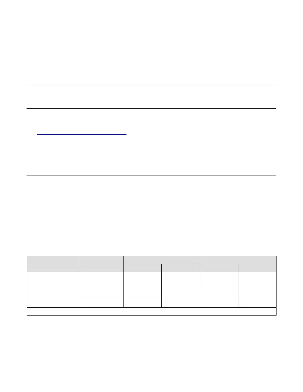
Table 3. Maximum Loop Wire Resistance per Logic Solver Output Voltage
(1)
Logic Solver Output
Voltage
(VDC)
Maximum Loop
Wire Resistance
(Ohms)
Maximum Wire Length - meters (feet)
(2)
22 AWG 20 AWG 18 AWG 16 AWG
24.00
23.75
23.50
23.25
23.00
32.0
27.0
22.0
17.0
12.0
290 (952)
245 (804)
200 (655)
154 (506)
109 (357)
435.6 (1429)
367.3 (1205)
299 (982)
231 (759)
163 (536)
725.7 (2381)
612.3 (2009)
499.0 (1637)
385.6 (1265)
272 (893)
967.7 (3175)
816.6 (2679)
665.4 (2183)
514.2 (1687)
363 (1190)
22.75
22.50
7.0
2.0
63.4 (208)
18 (60)
95.4 (313)
27 (89)
159 (521)
45.4 (149)
212 (694)
60.4 (198)
1. Maximums in this table assume a line conditioner and a solenoid that requires a minimum of 20.4 V and 42 mA to engage.
2. Wire length includes both wires in a twisted pair.
5. Proceed to Step 4—Configure the Digital Valve Controller on page 33.
 Loading...


