Quick Start Guide
D103556X012
DVC6200 Digital Valve Controllers
August 2015
42
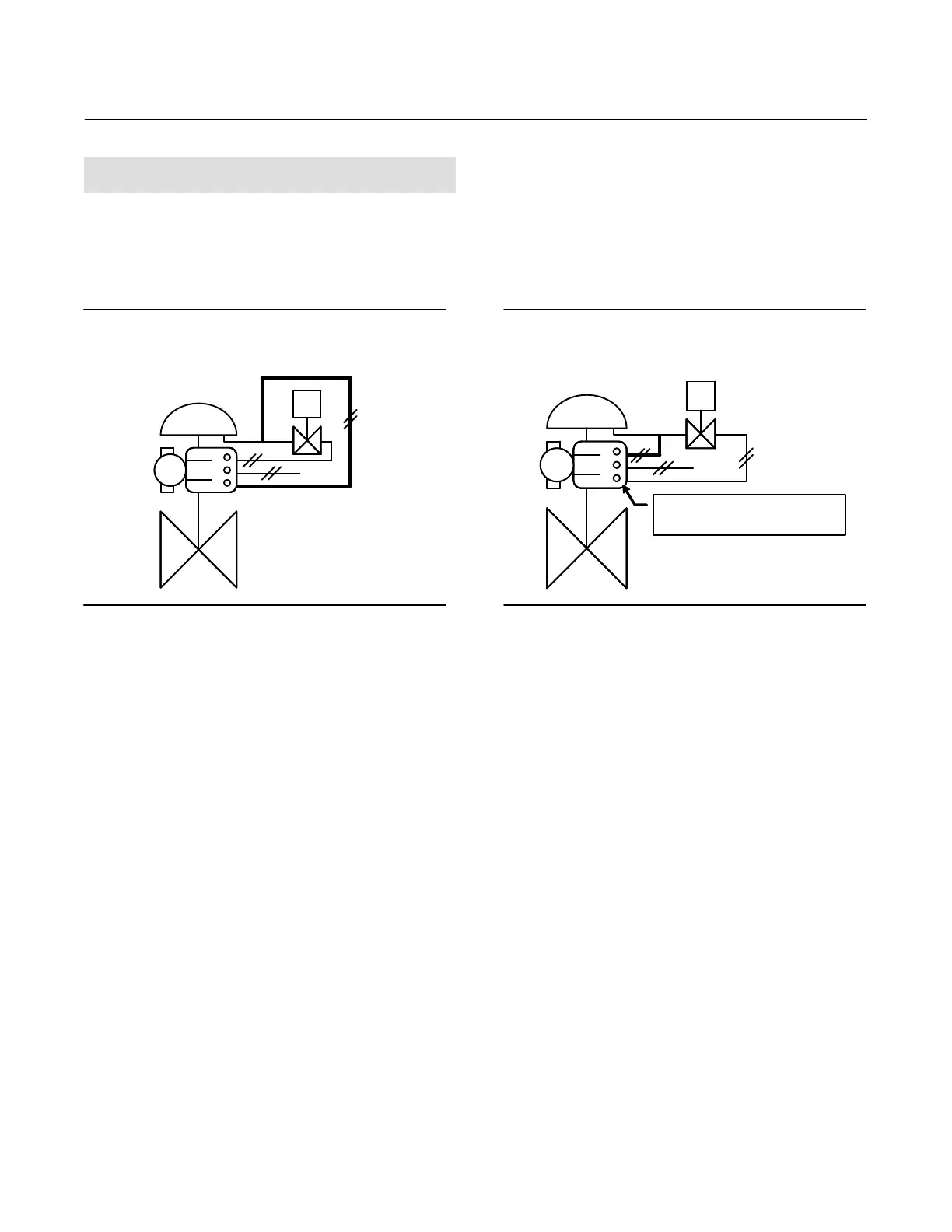
Solenoid Valve Health Monitoring
If a solenoid valve is installed between the DVC6200 SIS pressure output and the actuator, the control valve assembly
can be configured to verify the operation of the solenoid valve. This applies to singleacting actuator applications only.
The “unused” output port of the DVC6200 SIS is tubed such that the pressure downstream of the solenoid valve is
measured. When the solenoid valve is pulsed, the DVC6200 SIS senses the momentary pressure drop across the
solenoid valve.
Figure 35. Tubing for Solenoid Valve Health
Monitoring, DeEnergize to Trip DVC6200 SIS
AS
S
E1460
Figure 36. Tubing for Solenoid Valve Health
Monitoring, Energize to Trip DVC6200 SIS
AS
S
SINGLE-ACTING, REVERSE (RELAY B)
4 mA = FULL SUPPLY TO ACTUATOR
E1461
1. For DETT applications (figure 35):
D Install at least 10 mm (3/8inch) diameter tubing between output B (bottom port) of the DVC6200 SIS output and
D the tubing segment between the solenoid valve and safety valve actuator.
2. For ETT DVC6200 SIS applications (figure 36):
D Install at least 10 mm (3/8inch) diameter tubing between output A (top port) of the DVC6200 SIS output and the
D tubing segment between the solenoid valve and safety valve actuator.
3. Proceed to Step 4—Configure the Digital Valve Controller on page 33.

 Loading...


